
Control Valve Sizing: Kv and Cv Formula with a Worked Example
How to size a control valve for liquid: Kv and Cv defined, the sizing equation in metric and US units, choked flow checks, the datasheet a vendor needs and a worked example.
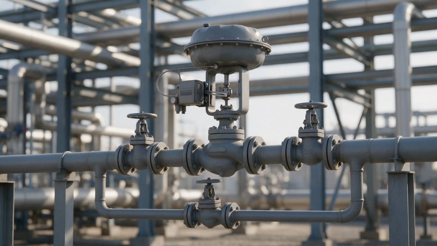
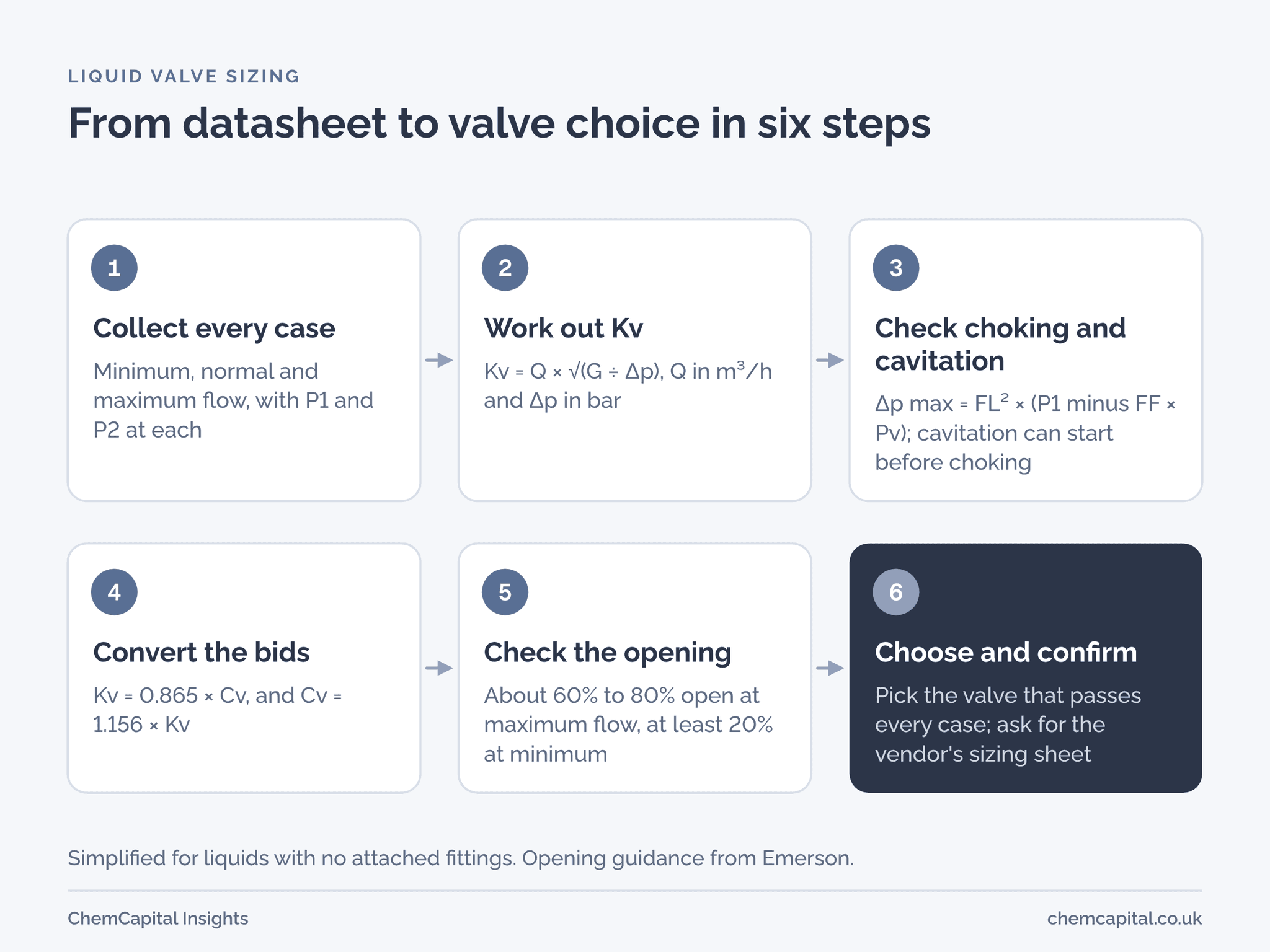
Control valve sizing means working out the flow coefficient a valve needs at every operating case, then choosing a valve whose rated coefficient covers the largest case and still controls well at the smallest. In metric units the coefficient is Kv: the flow of water in m³/h that gives a 1 bar pressure drop across the valve. US makers quote Cv: the flow of 60 °F water in US gallons per minute that gives a 1 psi drop. Kv is 0.865 × Cv, and Cv is 1.156 × Kv [1, 2, 3].
For a liquid in metric units the basic equation is Kv = Q × √(G ÷ Δp), with Q in m³/h, Δp the pressure drop across the valve in bar, and G the relative density, 1.0 for water [3]. Then check for choked flow, cavitation and how far open the valve will sit.
Why this matters now
Bids for one control valve can mix units: a European maker may state Kv and a US maker Cv, and for the same valve the Cv figure is about 16% higher. Imperial Cv also exists and differs slightly, so check which gallon a datasheet means [1].
Oversizing is the other trap. Michael McCarty of Emerson, writing in Chemical Processing in 2015, calls it a problem in many plants: an oversized valve can make the loop cycle, throttling close to its seat erodes the trim, and a typical equal percentage valve's turndown of about 30:1 can fall to 3:1 or less [4].
Join ChemCapital to streamline sourcing and connect with verified partners
Whether you're buying or supplying, ChemCapital gives you the tools to manage the complete procurement cycle in one platform.
Kv and Cv: what the numbers mean
| Term | What it means |
|---|---|
| Kv | Flow of water in m³/h, typically at 5 °C to 40 °C, that gives a 1 bar drop [1] |
| Cv (US) | Flow of water at 60 °F (16 °C) in US gallons per minute that gives a 1 psi drop [2] |
| Kvs | The stated Kv of a valve when fully open [1] |
| Converting | Kv = 0.865 × Cv; Cv (US) = 1.156 × Kv; Cv (Imperial) = 0.963 × Kv [1, 3] |
The liquid sizing equation in both unit systems
The ISA and IEC liquid method, as Emerson's Fisher catalogue sets it out, is Cv = Q ÷ (N1 × Fp × √(Δp ÷ G)) [3]. N1 is a units constant: 1.00 for US gpm with psi, 0.865 for m³/h with bar, and 0.0865 for m³/h with kPa. Fp corrects for reducers or other fittings attached to the valve and is 1.0 when there are none. G is the liquid's density at flowing temperature divided by the density of water at 60 °F [3].
With no fittings:
- US units: Cv = Q × √(G ÷ Δp), with Q in US gpm and Δp in psi.
- Metric units: Kv = Q × √(G ÷ Δp), with Q in m³/h and Δp in bar. Because Kv is 0.865 × Cv, the constant cancels.
The international standard is IEC 60534 Part 2 1, the sizing part of the IEC 60534 control valve series, in edition 2.0 of 2011 on the IEC webstore. Its liquid equations assume a Newtonian fluid and are not meant for slurries or liquid and solid conveyance [5]. A Reynolds number factor corrects for non turbulent flow, which matters with viscous liquids [3, 5], and a flashing liquid needs the choked flow check below [3].
Choked flow, cavitation and flashing
As the pressure drop rises past a limit, so much liquid vaporises inside the valve that the flow chokes [3]. The Fisher method caps the drop used in sizing at Δp max = FL² × (P1 minus FF × Pv), with absolute pressures [3]:
- FL is the liquid pressure recovery factor, from the vendor's coefficient tables.
- Pv is the vapour pressure at inlet temperature and Pc the critical pressure, with FF = 0.96 minus 0.28 × √(Pv ÷ Pc).
If the service drop is above Δp max, the flow is choked and the method sizes on Δp max instead. When the outlet pressure stays above the vapour pressure, the cause is cavitation; when it falls below, it is flashing [3].
Passing this check does not mean the valve is free of cavitation. Bubbles start to form and collapse, and can begin to do harm, at a much smaller pressure ratio, Δp ÷ (P1 minus Pv), than the one that chokes the flow [6]. Ask the vendor for the valve's incipient cavitation ratio, which Samson writes as xFZ, and compare it with every case.
In cavitation, vapour bubbles form where the pressure just past the seat dips below the vapour pressure, then collapse as the pressure recovers. The collapse pits the trim, the body and the downstream pipe, and makes noise and vibration. Hot liquids and a low outlet pressure both raise the risk, and large valves tend to suffer worse damage. One anti cavitation design splits the drop between a perforated cage and the plug. Flashing carries vapour on into the outlet pipe and cuts the valve's capacity [7]. Pumps face the same physics; see NPSH explained.
How far open the valve should sit
Rangeability is the ratio of the largest to the smallest flow coefficient over which the valve still follows its stated characteristic [2]. Emerson recommends a size that leaves the valve roughly 60% to 80% open at the highest flow you need and at least 20% open at the lowest. If it would have to work under 10% or over 90% of its travel, choose another size [4].
The opening at a given flow depends on the trim: on a linear trim, equal steps of travel give equal steps of Cv; on an equal percentage trim, each step changes Cv by the same percentage of its current value [2].
What the datasheet must give the vendor
The P&ID shows where the valve sits, not how to size it. Emerson's Control Valve Handbook opens its sizing chapter with a long checklist [8]. The essentials for a liquid duty:
| Datasheet item | What to give | Why the vendor needs it |
|---|---|---|
| Flow cases | Minimum, normal and maximum flow, plus start up and shutdown conditions | Sizing at every expected condition [4, 8] |
| Pressures | Inlet pressure and outlet pressure (or drop) at each case, and the drop at shutoff | Kv at each case and the shutoff duty [8] |
| Fluid | Fluid and all constituents, temperature, density, viscosity, vapour pressure | G, viscosity correction and the choked flow check [3, 8] |
| Noise | Maximum permissible noise level and where it is measured | So the vendor can check the valve against your limit [8] |
| Piping | Line size and schedule on both sides | Fp for reducers [3, 8] |
| Construction | Body material, end connections and rating, action on air failure, control signal | Mechanical selection [8] |
Practical example
Take an illustrative cooling water duty at 20 °C in a pumped loop. NIST gives water 998 kg/m³ at that temperature [9], so G is taken as 1.0. As flow falls, the pump gives more pressure and the line downstream loses less, so the valve drop rises.
| Case | Flow, m³/h | P1, barg | P2, barg | Δp, bar | Kv needed | Cv needed |
|---|---|---|---|---|---|---|
| Maximum | 40 | 5.0 | 3.0 | 2.0 | 28.3 | 32.7 |
| Normal | 30 | 5.4 | 2.6 | 2.8 | 17.9 | 20.7 |
| Minimum | 16 | 5.8 | 2.2 | 3.6 | 8.4 | 9.7 |
At maximum flow, Kv = 40 × √(1 ÷ 2.0) = 28.3, and Cv = 28.3 × 1.156 = 32.7.
Two vendors bid, both with linear trim (illustrative). Valve A has a rated Cv of 46 and FL of 0.85, so its Kvs is 46 × 0.865 = 39.8. Valve B has a rated Cv of 73 and FL of 0.60, so its Kvs is 63.1.
For the choked flow check, NIST gives water at 20 °C a vapour pressure of 0.023 bar and a critical pressure of 220.6 bar [9], so FF is 0.957 and FF × Pv is about 0.02 bar. At minimum flow, P1 is about 6.8 bar absolute (5.8 barg plus about 1 bar). Valve A's limit is 0.85² × (6.8 minus 0.02) = 4.9 bar, well above the 3.6 bar it must take. Valve B's is 0.60² × 6.78 = 2.4 bar, below 3.6 bar, and at normal flow its limit of 2.3 bar is below 2.8 bar. With the outlet far above the vapour pressure, valve B would cavitate rather than flash [3].
On an ideal linear trim the share of rated Kv is roughly the share of travel; an equal percentage trim sits much further open, so use the vendor's curve [2]. Valve B's choked cases are sized on Δp max:
| Case | Valve A opening | Valve B opening |
|---|---|---|
| Maximum | 71% | 45% |
| Normal | 45% | 31%, choked |
| Minimum | 21% | 16%, choked |
Valve A is the better choice: inside the 60% to 80% band at maximum flow, above 20% at minimum, and clear of choking [4]. Its cavitation margin still needs checking: at minimum flow its pressure ratio is 3.6 ÷ 6.78, about 0.53, against an FL² of 0.72, so ask its vendor for xFZ [6], a noise prediction and a sizing sheet for all three cases. Valve B is oversized and choked at its normal duty.
Send every bidder the same datasheet
Sizing often goes wrong at the enquiry: one flow, no pressures, no vapour pressure. ChemCapital sends one structured RFQ to all your suppliers at once, so every bidder sizes from the same process data and you compare the replies side by side. When quotes arrive, AI Quotation Comparison extracts price, lead time, materials, certifications and scope from each for you to review. The sizing check stays with your engineer.
Ready to send every valve bidder the same process data? Start free with ChemCapital.
Frequently asked questions
How do you convert Kv to Cv?
Multiply Kv by 1.156 to get US Cv, and multiply Cv by 0.865 to get Kv. Imperial Cv is slightly different, about 0.963 times Kv, so check which gallon a datasheet uses.
What is the Cv formula for liquids?
For a liquid with no attached fittings, Cv = Q × √(G ÷ Δp), with Q in US gallons per minute, Δp in psi and G the relative density. In metric units the same form gives Kv, with Q in m³/h and Δp in bar, provided the flow is turbulent and not choked or flashing.
How open should a control valve be at maximum flow?
Emerson recommends roughly 60% to 80% open at the highest required flow and at least 20% open at the lowest. A valve that would work under 10% or over 90% of its travel is the wrong size.
What data does a vendor need to size a control valve?
Minimum, normal and maximum flow with inlet and outlet pressure at each case, plus fluid temperature, density, viscosity and vapour pressure. Add the shutoff pressure drop, permissible noise level, line size and schedule, and the action on air failure.
Informational only, not procurement or legal advice. Cited names, frameworks, and statistics belong to their respective owners.
Join ChemCapital to streamline sourcing and connect with verified partners
Whether you're buying or supplying, ChemCapital gives you the tools to manage the complete procurement cycle in one platform.
Get started freeRelated articles
NPSH Explained: NPSHa vs NPSHr with a Worked Example
NPSHa is what your suction system gives a pump; NPSHr is what the pump needs. How to calculate NPSHa, what margin to ask for and how to check it on pump bids.
How to Read a P&ID: A Line by Line Guide for Engineers and Buyers
How to read a P&ID line by line: equipment tags, line numbers, valves and ISA instrument letters, and what a buyer takes from the drawing to build RFQs.

Technical Bid Evaluation for Process Equipment: Step by Step
A technical bid evaluation decides which bids meet your specification before prices are compared. The steps, who takes part, common mistakes and a pump example.