
Hydrostatic Test Pressure: How Each Code Sets It, with Examples
Hydrostatic test pressure is a code multiple of design pressure, corrected for temperature. How ASME VIII, EN 13445, PD 5500 and B31.3 set it, with a worked example.
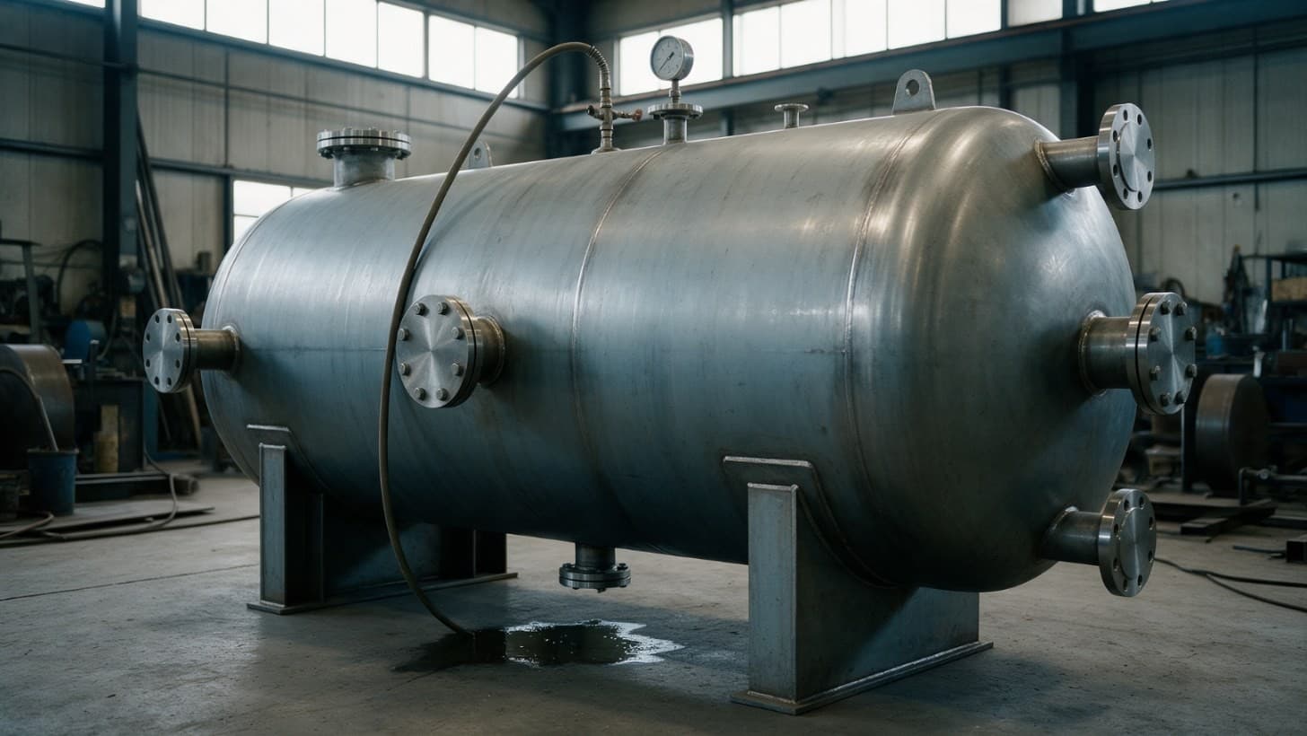
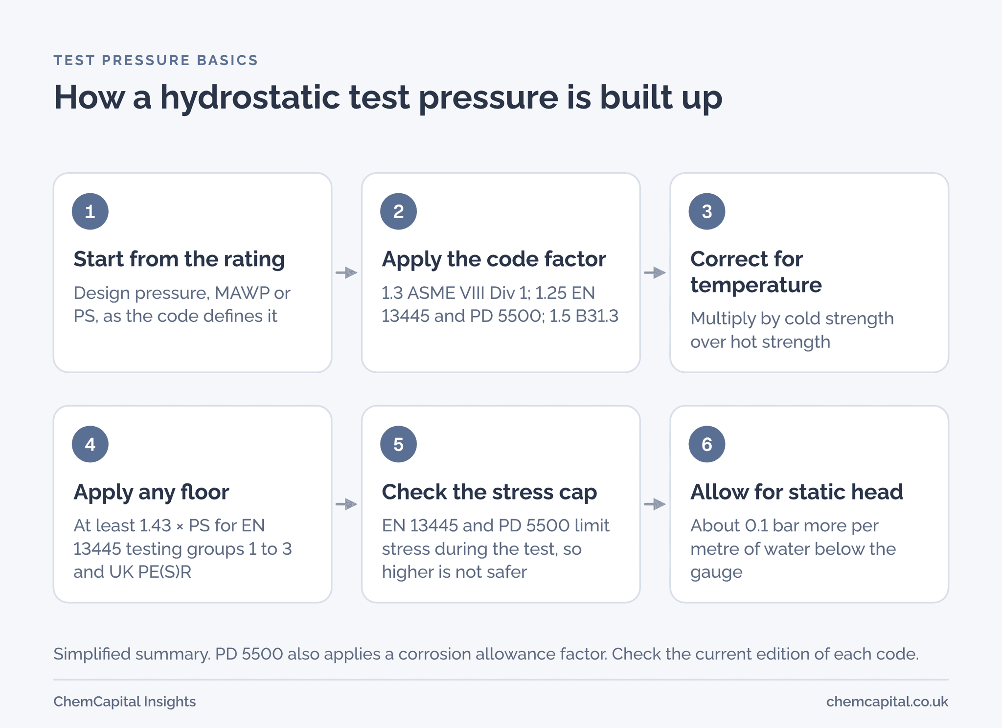
Hydrostatic test pressure is the pressure a finished vessel or piping system is taken to, full of water, before it goes into service, to prove its strength and tightness. Every major code sets it the same way: a multiple of the design pressure, raised further when the equipment will run hot, because the test is done cold. ASME VIII Division 1 uses 1.3 times the maximum allowable working pressure (MAWP). EN 13445 sets a floor of 1.43 times the maximum allowable pressure for testing groups 1 to 3, and UK regulations for new pressure vessels apply the same floor as a general rule. ASME B31.3 process piping uses 1.5 times the design pressure [1, 2, 3, 5].
So one vessel can carry different test pressures under different codes.
Why this matters now
A UK buyer can receive quotes for one vessel from fabricators working to ASME VIII, EN 13445 and PD 5500. A test pressure that looks high or low against another bid usually reflects the code, not a stronger or weaker vessel. The RFQ (request for quotation) should name the code, and each bid should show how its test pressure follows from it.
The test is also usually one of the last hold points before dispatch in the ITP, the inspection and test plan. Finding then that the pressure was worked out on the wrong basis means a retest, a new certificate and a late delivery.
A water test is safer than a gas test, but not risk free. In December 1965 a 167 tonne ammonia converter built for ICI at Immingham failed during its hydraulic proof test, at 34 N/mm² against a required 48 N/mm², with the water below 10 °C. Fine cracks in the steel beside a flange weld, and weld metal left with poor toughness because its heat treatment fell short, were the causes. A fragment of about 2 tonnes was thrown out of the building and landed about 46 m away [4]. The investigation recommended testing above the ductile brittle transition temperature, the point below which steel can break with little warning [4].
Join ChemCapital to streamline sourcing and connect with verified partners
Whether you're buying or supplying, ChemCapital gives you the tools to manage the complete procurement cycle in one platform.
The stress ratio: why hot equipment is tested higher
Steel is weaker hot than cold. Equipment designed for 250 °C is tested at workshop temperature, where the metal is stronger, so a plain multiple of design pressure would test it too gently. The codes correct for this with a stress ratio: the allowable stress at test temperature divided by that at design temperature. EN 13445 calls them nominal design stresses and PD 5500 design strengths; the idea is the same.
The detail differs by code. ASME VIII Division 1 takes the lowest ratio among the vessel's pressure parts [1]. The EN 13445 Part 5 summary we reviewed uses the highest ratio among the materials of the main pressure parts, such as the shell and ends [5]. On a vessel built from more than one grade, ask which material set the ratio.
How each code sets the test pressure
Three of the public sources describe earlier editions, so check the current edition before relying on a factor.
| Code | Hydrostatic test pressure, in words | Points to note |
|---|---|---|
| ASME VIII Division 1 (vessels) | 1.3 × MAWP × the lowest stress ratio [1, 6] | Editions before the 1999 addenda used 1.5. Pneumatic test: 1.1 × MAWP × ratio [1, 6] |
| EN 13445 Part 5 (vessels) | For testing groups 1, 2 and 3: the greater of 1.25 × PS × stress ratio and 1.43 × PS, where PS is the maximum allowable pressure [5] | Testing groups set how much non destructive testing (NDT) the welds receive; check the current standard for group 4. Reduced if the test would exceed the stress allowed for test conditions [5] |
| PD 5500 (vessels) | 1.25 × design pressure × design strength ratio (ambient over design temperature) × shell thickness ÷ (thickness less corrosion allowance), from a summary of an earlier edition [7] | Above 1.08 × the standard test pressure, a check keeps membrane stress within 90% of minimum yield [7] |
| ASME B31.3 (process piping) | 1.5 × design pressure, corrected for temperature [3, 6] | Since the 2014 edition, the leak examination may be done after reducing to design pressure [3] |
| UK Pressure Equipment (Safety) Regulations 2016 (vessels) | At least the greater of 1.25 × the pressure at maximum service loading, allowing for maximum allowable temperature, and 1.43 × PS | Applies as a general rule to vessels that must meet the essential safety requirements [2] |
More pressure is not better: EN 13445 and PD 5500 both limit the stress during the test [5, 7]. When a skid is tested as one assembly, every hose and connector in the test circuit must be rated for the test pressure and medium [8], and anything rated lower, such as some instruments, should be removed or isolated. Our factory acceptance test checklist covers the rest.
Also, the gauge reading is not the pressure everywhere: each metre of water adds about 0.1 bar (1,000 kg/m³ × 9.81 m/s² × 1 m is 9,810 Pa). PD 5500 requires the static head to be considered for vertical vessels [7], and tall columns are usually tested lying horizontal, because an upright test raises the pressure at the bottom [1].
Hydraulic first: what HSE expects
HSE guidance note GS4 covers pressure test safety. Its first recommendation is to fill with water or another liquid and keep gas for cases where a liquid cannot be used, because that cuts the energy stored in the test [8]. It also asks for:
- a written safe system of work for the test [8]
- venting of air before a liquid test is pressurised [8]
- a low pressure check first, then pressure raised in stages with holds [8]
- protection against overpressure, normally a relief valve [8]
- segregation, with a full enclosure preferred over barriers [8]
A pneumatic test runs at a lower pressure, 1.1 times MAWP times the stress ratio under ASME VIII Division 1 [1, 6], but compressed gas stores more energy than pressurised water. Under the Pressure Equipment (Safety) Regulations 2016, other tests may replace the hydrostatic test only where it is harmful or impractical, and only after additional measures such as NDT [2]. This is general information, not legal advice.
What to put in the RFQ, the ITP and the certificate
In the RFQ, give the design code and edition, design pressure, MAWP or PS, and design temperature for each chamber. Ask every bidder to state:
- the calculated test pressure and the formula behind it
- the stress ratio and which material set it
- the test position, the gauge height and the pressure at the lowest point
- the test medium, the water quality and the minimum metal temperature during the test
- the hold or witness points for you and any approved body, notified body or third party inspector
When the certificate arrives, check it matches the nameplate serial number, drawing revision, code and edition. It should show the required pressure, the pressure actually held, the hold time, calibrated gauge serial numbers, the medium and its temperature, the result, and signatures from the fabricator and the witness. Query any certificate that states a pressure with no basis before you release the hold point.
Practical example
Take an illustrative stainless steel receiver, 3 m tall, with a design pressure of 10 barg (bar gauge). MAWP and PS are taken as equal to the design pressure; ASME offers a test option based on the design pressure of the whole vessel [1]. The stress ratios are illustrative; real values come from each code's material tables for the grade and can differ between ASME and EN 13445. The EN 13445 figures assume testing group 1, 2 or 3.
| Item | Case A: designed for 50 °C | Case B: designed for 250 °C |
|---|---|---|
| Stress ratio (illustrative) | 1.00 | 1.20 |
| ASME VIII Division 1: 1.3 × 10 × ratio | 13.0 barg | 15.6 barg |
| EN 13445: 1.25 × 10 × ratio | 12.5 barg | 15.0 barg |
| EN 13445: 1.43 × 10 | 14.3 barg | 14.3 barg |
| EN 13445 test pressure (greater value) | 14.3 barg | 15.0 barg |
| Higher test | EN 13445, by 1.3 bar | ASME, by 0.6 bar |
In case A the 1.43 floor governs and the EN 13445 test is 10% higher. In case B the stress ratio lifts both and the ASME factor of 1.3 overtakes. The crossover is a ratio of 1.10, where 1.3 × 1.10 equals 1.43.
Tested upright with the gauge at the top, the bottom sees about 0.29 bar more: about 14.6 barg in case A under EN 13445.
For a UK buyer, case A is the one to watch. If this vessel must meet the Pressure Equipment (Safety) Regulations 2016, the 1.43 × PS rule applies as a general rule whatever the design code, so the ASME vessel would normally be tested at 14.3 barg, not 13.0 barg, unless the manufacturer shows an equivalent overall level of safety [2].
Agree the test basis before you order
A test pressure is cheap to agree at RFQ stage and expensive to argue about at the hold point. ChemCapital sends one structured RFQ to all your suppliers at once, so every bidder receives the same questions you set on code, design conditions and testing, and you compare the replies side by side. After award, a timestamped audit trail records each revision and decision.
Ready to put every bidder on the same test basis? Start free with ChemCapital.
Frequently asked questions
How do you calculate hydrostatic test pressure?
Multiply the design pressure or MAWP by the code factor and by the stress ratio, which is the allowable stress at test temperature divided by that at design temperature. ASME VIII Division 1 uses 1.3, EN 13445 uses 1.25 with a floor of 1.43 times the maximum allowable pressure for testing groups 1 to 3, and ASME B31.3 piping uses 1.5.
Is hydrotest pressure 1.5 times design pressure?
For ASME B31.3 process piping, yes, corrected for temperature. For ASME VIII Division 1 vessels the factor has been 1.3 times MAWP since the 1999 addenda; 1.5 was the earlier rule.
Why is hydrostatic testing preferred over pneumatic testing?
Compressed gas stores more energy than pressurised water, so a failure during a gas test releases more. HSE guidance tells you to test with water or another liquid and to use gas only when a liquid is not practicable.
What is the minimum test pressure for a pressure vessel in the UK?
For vessels that must meet the Pressure Equipment (Safety) Regulations 2016, Schedule 2 sets at least the greater of 1.25 times the pressure at maximum service loading, allowing for temperature, and 1.43 times the maximum allowable pressure. It applies as a general rule, and a manufacturer departing from it must show an equivalent overall level of safety.
Continue reading
Informational only, not procurement or legal advice. Cited names, frameworks, and statistics belong to their respective owners.
Join ChemCapital to streamline sourcing and connect with verified partners
Whether you're buying or supplying, ChemCapital gives you the tools to manage the complete procurement cycle in one platform.
Get started freeRelated articles
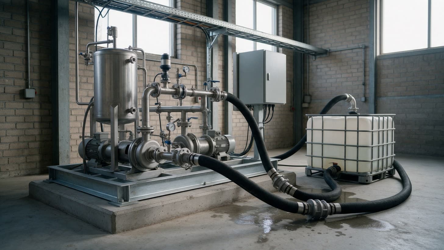
Site Acceptance Test (SAT) Checklist for Process Skids
What a site acceptance test must prove once a skid is installed, how SAT differs from FAT and commissioning, a full SAT checklist and how to handle failed tests.
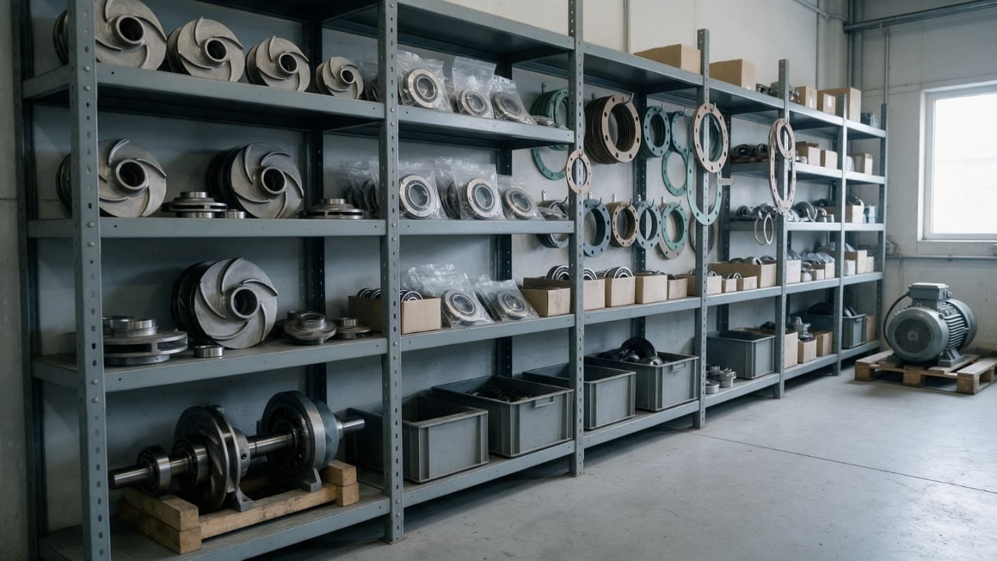
Recommended Spares List: Commissioning, Operating and Insurance Spares
What a recommended spares list should hold: commissioning, two year operating and insurance spares, criticality, what to ask in the RFQ, and a pump and vessel template.
Punch List Categories and Mechanical Completion for Process Plant
What a punch list is, how category A, B and C items gate mechanical completion, start up and handover, who clears them, and a template for vendor equipment packages.