
LMTD Calculation: Heat Exchanger Sizing Worked Example
How to calculate LMTD, the correction factor F and heat exchanger area, worked through for a water cooler, plus what a temperature cross does to the area.
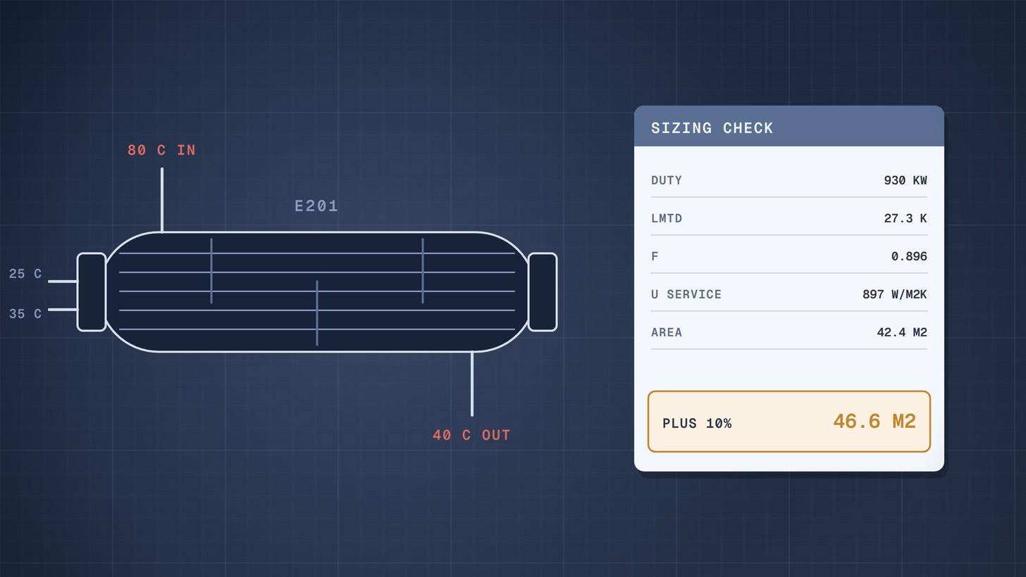
The log mean temperature difference (LMTD) is the average driving force in a heat exchanger: the difference between the two end temperature differences, divided by the natural log of their ratio. Required area then follows from Q = U × A × F × LMTD. In the worked example below, cooling 20,000 kg/h of process water from 80 °C to 40 °C with tower water at 25 °C to 35 °C gives an LMTD of 27.3 K, a correction factor of 0.90 and about 47 m² of area with a 10% margin.
You do not need to design the exchanger to use this. As a buyer, the same five numbers let you check whether a supplier's offered area, U value and temperatures hang together.
Why this matters now
Heat exchanger bids differ in area, U value and fouling allowance, and the cheapest bid often has the least area. Without a quick check, a bid with optimistic assumptions looks like good value until the exchanger fails to hold its outlet temperature in the first summer.
The duty and the allowed temperatures also decide the type and shape of the exchanger. A close temperature approach, or a cold outlet that rises above the hot outlet, can force two shells in series or a different type altogether. Knowing that before the RFQ goes out saves a round of requotes. Our guide to TEMA heat exchanger types covers the shell and head options.
Create and manage RFQs in minutes
ChemCapital handles the entire procurement cycle, from structured RFQs and supplier comparisons to formal purchase orders and delivery tracking.
The method in five steps
- Heat duty. Q = m × cp × ΔT on the side you know best. The other side's flow or outlet temperature follows from the same Q.
- LMTD for counter current flow. Take the temperature difference at each end of the exchanger, then LMTD = (ΔT₁ minus ΔT₂) ÷ ln(ΔT₁ ÷ ΔT₂). The Chemical Engineer gives the same formula using the greater and lesser terminal temperature differences [1].
- Correction factor F. Real shell and tube exchangers with more than one tube pass are not pure counter current, so the LMTD is multiplied by F, which is 1.0 for pure counter current and less for other arrangements [2].
- U value. The overall coefficient including fouling, from experience, a supplier or a rating program.
- Area. A = Q ÷ (U × F × LMTD), plus any design margin.
The correction factor and the temperature cross
For a shell with one shell pass and two (or any even number of) tube passes, F depends on two ratios [2]:
- P = (t₂ minus t₁) ÷ (T₁ minus t₁), the temperature effectiveness of the tube side fluid
- R = (T₁ minus T₂) ÷ (t₂ minus t₁), the ratio of the hot side temperature change to the cold side change
Here T is the shell side fluid, t is the tube side fluid, 1 is the inlet and 2 is the outlet. F comes from the standard charts or from the closed form equation for this arrangement, which Subramanian's Clarkson University notes set out [2].
The Chemical Engineer advises not to use arrangements where F is below 0.75, and says 0.85 is even better [1]. Subramanian adds a subtler point: avoid the steep part of the F curves, because a small error in temperatures there gives a large change in F [2].
Low F usually signals a temperature cross, where the cold fluid leaves hotter than the hot fluid leaves. The Chemical Engineer notes that designers dislike crosses because they degrade the LMTD so much, and lists three ways out: more cold side flow to lower its outlet temperature, more shell side passes, or two exchangers in series [1].
Worked example: cooler E201
E201 cools treated process water from 80 °C to 40 °C using cooling tower water that enters at 25 °C and may leave at 35 °C. The flows, U value and fouling allowance are illustrative. The water properties are sourced.
Step 1: duty. Hot side flow is 20,000 kg/h, or 5.556 kg/s. The specific heat of water at the mean temperature of 60 °C is 4.185 kJ/kg K [3].
Q = 5.556 × 4.185 × (80 minus 40) = 930 kW.
Cooling water flow for a 10 K rise, with cp of 4.178 kJ/kg K at 30 °C [3]: 930 ÷ (4.178 × 10) = 22.26 kg/s, or about 80,100 kg/h.
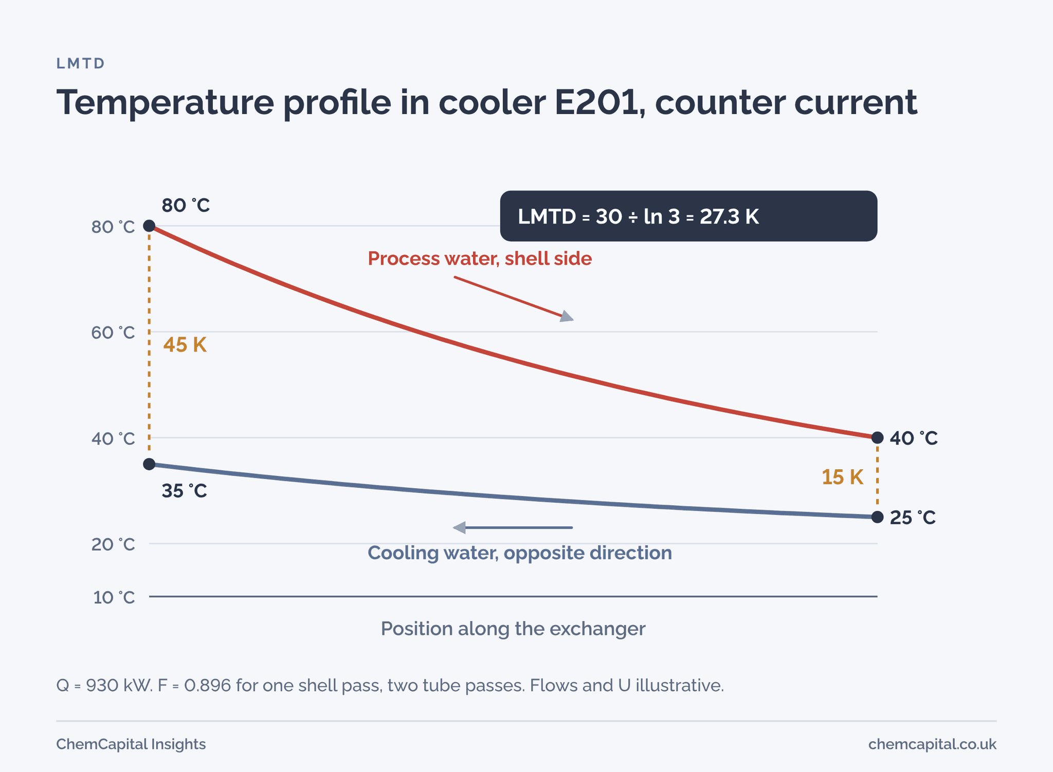
Step 2: LMTD. In counter current flow, the hot inlet meets the cold outlet.
- Hot end: 80 minus 35 = 45 K
- Cold end: 40 minus 25 = 15 K
- LMTD = (45 minus 15) ÷ ln(45 ÷ 15) = 30 ÷ 1.0986 = 27.3 K
If the same streams ran co current, the end differences would be 55 K and 5 K, and the LMTD only 20.9 K. Counter current flow needs about 24% less area for the same duty.
Step 3: correction factor. With the process water on the shell side in a one shell pass, two tube pass exchanger: R = 40 ÷ 10 = 4.0 and P = 10 ÷ 55 = 0.182. The equation gives F = 0.896, comfortably above 0.75.
Step 4: U value. For water to water exchangers, Engineering ToolBox lists typical overall coefficients of 900 to 2,500 W/m² K [4]. Take a clean U of 1,400 W/m² K. The Chemical Engineer's worked example uses a fouling resistance of 0.0002 m² K/W for cooling water [1]; allow the same on each side here. Then:
1 ÷ U = 1 ÷ 1,400 + 0.0002 + 0.0002 = 0.001114, so U = 897 W/m² K in service.
Step 5: area. A = 930,000 ÷ (897 × 0.896 × 27.3) = 42.4 m². The Chemical Engineer's example adds a 10% safety margin [1], giving about 46.6 m².
Fouling made a big difference here. With a clean U of 1,400, the area would be only 27.2 m². The two fouling resistances raised the required area by more than half, in line with the article's warning that fouling can cut U by as much as 50% when the film coefficients are high [1].
What happens if you squeeze the cooling water
Cooling water costs money to pump and treat, so it is tempting to let it leave hotter. Run the same E201 duty with less cooling water:
| Cooling water outlet | Cooling water flow | LMTD | F (one shell, two tube passes) | Area at U 897 |
|---|---|---|---|---|
| 35 °C | 80,100 kg/h | 27.3 K | 0.90 | 42.4 m² |
| 40 °C | 53,400 kg/h | 25.5 K | 0.81 | 50.3 m² |
| 45 °C | 40,100 kg/h | 23.6 K | 0.66 | 66.9 m² |
| 50 °C | 32,100 kg/h | 21.6 K | no solution | needs two or more shells in series |
At 45 °C the cooling water leaves 5 K above the process water outlet, a temperature cross. F drops to 0.66, below the 0.75 guide, and the area grows by nearly 60%. At 50 °C a single shell of this type cannot do the duty at all. This is the kind of result a buyer should see before fixing the cooling water figures in the RFQ.
Checking a supplier's offer
A heat exchanger datasheet from a bidder should let you repeat this calculation. Check five things:
- Duty and temperatures match your process data on both sides. A small change in an outlet temperature can hide a big change in LMTD.
- LMTD and F. Recompute them. An F below about 0.75 means the arrangement is working on the steep part of the curve.
- U value. Compare the service U with typical ranges and with the other bids. A U far above the others needs an explanation.
- Fouling resistances. They should match what you specified on each side. A bid that uses lower fouling than specified will show less area.
- Area and margin. Offered area divided by required area shows the real margin. State in the RFQ whether margin is on area or on U.
Our heat exchanger datasheet guide lists the fields to send, and the plate vs shell and tube comparison helps when a close approach makes a plate exchanger worth quoting. Alfa Laval, a plate exchanger maker, says its gasketed plate units can reach approach temperatures as close as 1 °F, about 0.6 K [5]; treat that as the maker's claim and check it on the offer.
ChemCapital's AI quotation comparison puts each bid's duty, area, U value, fouling allowance and price side by side, so the bid with the thinnest assumptions is easy to see.
Turning the numbers into an RFQ
Send every bidder the same duty, inlet and outlet temperatures on both sides, flows, fluid properties, fouling resistances, allowed pressure drops and the margin rule. Ask for U, F, LMTD and area in the offer. With those, the five step check above takes a few minutes per bid.
Ready to send heat exchanger RFQs that every supplier rates on the same basis? Start a free 14 day ChemCapital trial, with no credit card needed.
Frequently asked questions
How do you calculate LMTD?
Take the temperature difference between the two fluids at each end of the exchanger. LMTD is the difference between those two end values divided by the natural log of their ratio. For counter current flow, pair the hot inlet with the cold outlet at one end, and the hot outlet with the cold inlet at the other.
What is the LMTD correction factor F?
F corrects the counter current LMTD for exchangers that are not pure counter current, such as a shell with two tube passes. It depends on the temperature ratios P and R, is 1.0 for pure counter current, and arrangements with F below about 0.75 are generally avoided.
What is a temperature cross in a heat exchanger?
A temperature cross happens when the cold fluid leaves hotter than the hot fluid leaves. It cuts the correction factor sharply in a single shell with two tube passes, and the usual cures are more cold side flow, more shell side passes or two exchangers in series.
How do you calculate heat exchanger area from LMTD?
Divide the heat duty by the product of the overall heat transfer coefficient, the correction factor and the LMTD: A = Q ÷ (U × F × LMTD). Use a service U that includes fouling, then add any design margin you specify.
Continue reading
Informational only, not procurement or legal advice. Cited names, frameworks, and statistics belong to their respective owners.
Create and manage RFQs in minutes
ChemCapital handles the entire procurement cycle, from structured RFQs and supplier comparisons to formal purchase orders and delivery tracking.
Start for freeRelated articles
Pipe Thermal Expansion: Worked Example
How to calculate pipe thermal expansion for carbon and stainless steel, what restrained expansion does, and how loops and expansion joints absorb it.
Horizontal Tank Volume When Partly Filled: Worked Example
How to calculate the volume of a partly filled horizontal tank with dished heads, with a worked example and a full dip table you can rebuild in a spreadsheet.
Cooling Water Flow Calculation: Worked Example
How to calculate cooling water flow from heat duty and temperature rise, then size the cooling tower circulation, evaporation and make up water.