
Relief Valve Sizing to API 520: Worked Examples and the PSV Datasheet
Two worked API 520 relief valve sizing examples, one gas and one liquid, how to pick the API 526 orifice letter, and the PSV datasheet fields every RFQ needs.
Relief valve sizing to API 520 means working out the smallest flow area that can pass the required relief rate at the allowed overpressure, then choosing the next larger standard orifice letter, D to T. Below are two worked examples, one gas and one liquid, and the datasheet fields an RFQ needs so every supplier quotes the same valve.
Read this as a buyer's guide to the numbers, not a design method. Relief sizing must be done, or checked, by a competent engineer who owns the relief cases. What you can do as the buyer is make sure the datasheet is complete, recognise a sensible orifice choice and check that each quote meets the required capacity.
Why this matters now
The current edition is the tenth edition of API 520 Part I, Sizing and Selection, which API has published and sells through its webstore [1]. Standards sellers list it as October 2020 and describe its scope: relief devices for refineries, chemical plants and related industries, on equipment with a maximum allowable working pressure (MAWP) of 15 psig (103 kPa gauge) or more [2]. It sizes for steady flow of Newtonian fluids and points to API 521 for protecting equipment against failure from the heat of a fire [2].
Many relief valve RFQs still go out as a line on a valve list: "PSV, 2 inch, set 10 barg". That leaves each supplier to guess the fluid, the case and the back pressure. The quotes that come back cannot be compared, and an undersized valve can slip through. A complete datasheet fixes both problems, and you only need a few equations to read it with confidence.
If the terms are new, start with our guide to safety valves, relief valves and bursting discs and the one on design pressure, MAWP and operating pressure.
Create and manage RFQs in minutes
ChemCapital handles the entire procurement cycle, from structured RFQs and supplier comparisons to formal purchase orders and delivery tracking.
The sizing method in five steps
Every API 520 calculation follows the same path.
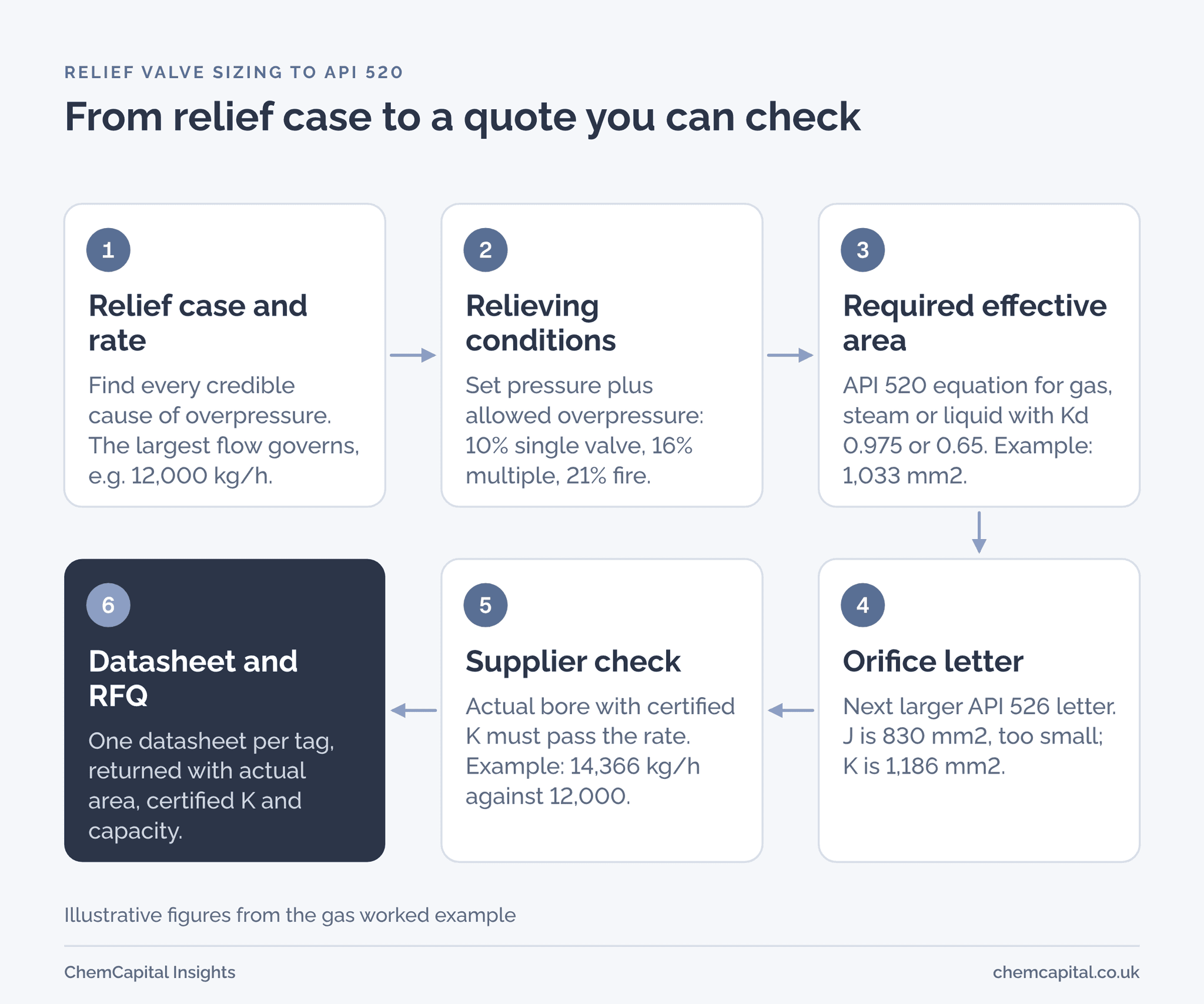
- Relief case and rate. The process engineer identifies the credible overpressure causes (blocked outlet, control valve failure, fire, exchanger tube rupture) and the flow each one produces. The largest governs. This step needs the most judgement and causes most errors.
- Relieving conditions. Set pressure plus allowed overpressure gives the relieving pressure. Under ASME Section VIII, accumulation above MAWP is limited to 10% for a single valve, 16% for multiple valves and 21% in a fire case [3].
- Required effective area. Apply the API 520 equation for the phase: gas, steam or liquid.
- Orifice letter. Pick the next larger standard letter from API 526.
- Supplier check. The supplier confirms the selection with its certified coefficient and actual bore, and states the certified capacity.
The coefficients used in step 3 are generic API values for preliminary sizing: an effective discharge coefficient (Kd) of 0.975 for gas and steam and 0.65 for liquid [4]. The correction factors are Kb for back pressure on gas, Kw for back pressure on liquid, Kc for a bursting disc fitted upstream and Kv for viscosity. Kc is 1.0 with no disc and 0.9 for a disc and valve combination that has not been certified [4].
Worked example 1: gas or vapour relief
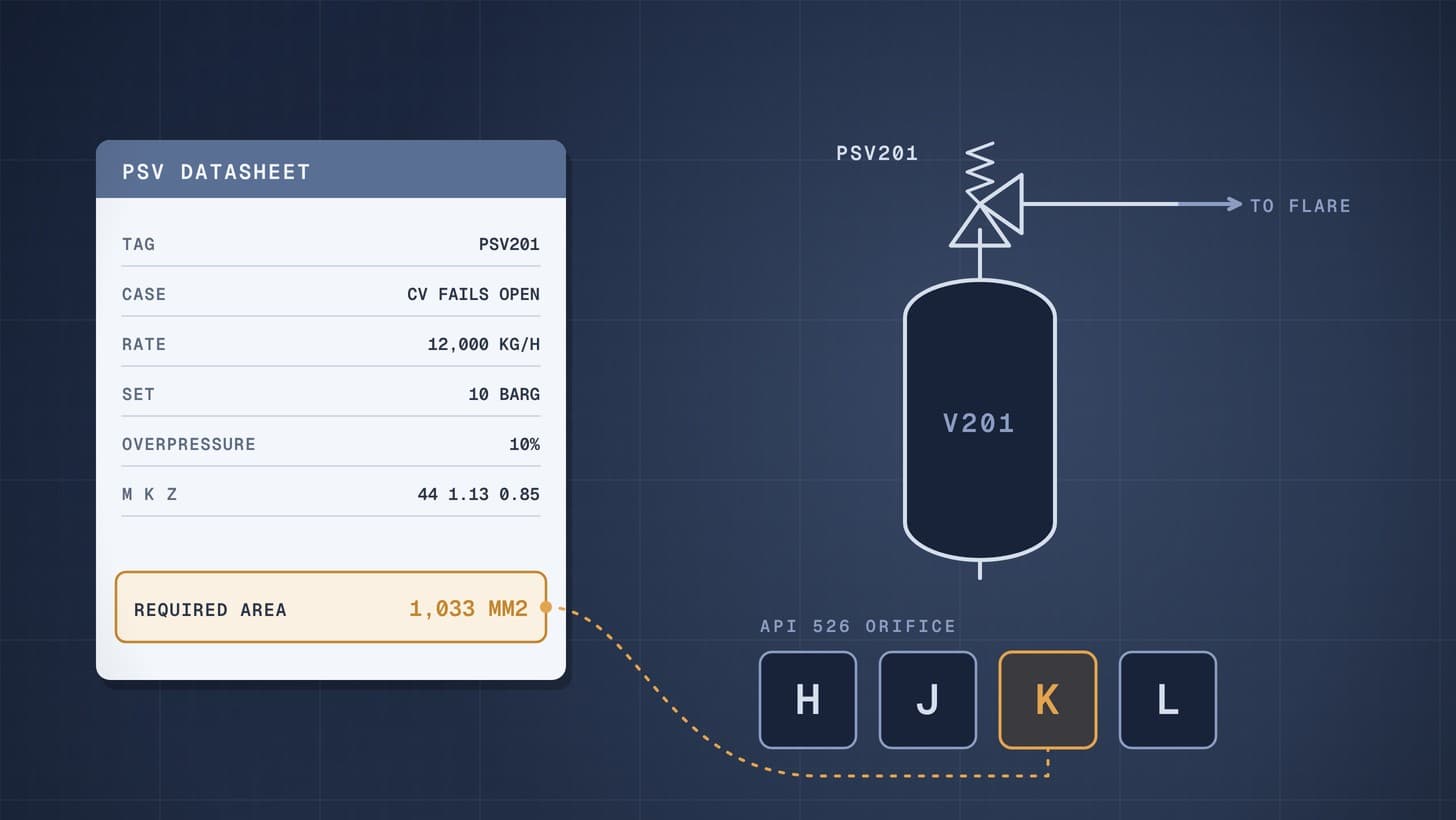
All figures here are illustrative. Vessel V201 has an MAWP of 10 barg. Its relief valve, PSV201, is set at 10 barg. The governing case is a control valve failing open upstream, giving a hydrocarbon vapour relief of 12,000 kg/h. Relieving properties from the process simulation: molecular weight (M) 44, ratio of specific heats (k) 1.13, relieving temperature (T) 330 K, compressibility (Z) 0.85. The valve discharges to a flare header at about 150 kPa absolute.
Relieving pressure. With a single valve, overpressure is 10%, so:
P1 = 1,000 kPa gauge × 1.10 + 101.3 = 1,201.3 kPa absolute.
Check for critical flow. Gas flow through the nozzle is critical (choked) when the back pressure is below the critical flow pressure. From the isentropic nozzle relation, that is P1 × (2 ÷ (k + 1))^(k ÷ (k minus 1)), or 0.578 × 1,201.3 = 695 kPa absolute for this gas. The flare header at 150 kPa absolute is far below that, so the critical flow equation applies. If it were not, API 520 has a separate subcritical equation [4].
Required area. In SI units (kg/h, kPa absolute, K, mm²) the API 520 critical flow equation is [4]:
A = W ÷ (C × Kd × P1 × Kb × Kc) × √(T × Z ÷ M)
where C = 0.03948 × √(k × (2 ÷ (k + 1))^((k + 1) ÷ (k minus 1))). For k = 1.13, C = 0.02505. With a conventional valve and no bursting disc, Kb and Kc are taken as 1 here; the engineer confirms Kb from the back pressure study.
A = 12,000 ÷ (0.02505 × 0.975 × 1,201.3 × 1 × 1) × √(330 × 0.85 ÷ 44) = 1,033 mm² (1.60 in²).
Orifice letter. J has an effective area of 1.287 in², or 830 mm², which is too small. K has 1.838 in², or 1,186 mm² [4]. So PSV201 is a K orifice, typically offered as a 3K4 valve (3 inch inlet, 4 inch outlet) [5].
Worked example 2: liquid relief
Again illustrative. Pump P101A can deadhead against a closed downstream valve, so PSV202 on its discharge must pass the full pump flow of 600 L/min of a water like liquid (specific gravity G = 1.0). It is set at 8 barg and discharges to an atmospheric drain.
Relieving pressure. At 10% overpressure, p1 = 800 × 1.10 = 880 kPa gauge. Back pressure p2 is 0 kPa gauge.
Required area. The API 520 liquid equation in SI units (L/min, kPa gauge, mm²) is [4]:
A = 11.78 × Q ÷ (Kd × Kw × Kc × Kv) × √(G ÷ (p1 minus p2))
With Kd = 0.65, and Kw, Kc and Kv all 1 (conventional valve to atmosphere, no disc, low viscosity):
A = 11.78 × 600 ÷ 0.65 × √(1.0 ÷ 880) = 367 mm² (0.568 in²).
Orifice letter. G is 0.503 in², or 325 mm², too small. H is 0.785 in², or 506 mm² [4]. So PSV202 is an H orifice, offered as 1½H3 or 2H3 [5].
Viscosity matters. For viscous liquids, Kv falls below 1. In the tenth edition, Kv = 1 ÷ √(1 + 170 ÷ Re) for Reynolds numbers above 80; at a Reynolds number of 4,525 it is about 0.98 [4]. A thick resin or a cold oil can push the valve up a letter, so viscosity at relieving temperature belongs on the datasheet.
Orifice letters: what they are and what they are not
The letters are a purchase designation. API 526, now in its eighth edition (August 2023), is a purchase specification for flanged steel relief valves. It fixes orifice designation and area, inlet and outlet sizes and ratings, materials, pressure and temperature limits, and centre to face dimensions [6]. That lets you swap one maker's K valve for another's without repiping.
| Letter | API effective area (in²) | API effective area (mm²) | Typical sizes |
|---|---|---|---|
| D | 0.110 | 71 | 1D2 |
| E | 0.196 | 126 | 1E2 |
| F | 0.307 | 198 | 1½F2 |
| G | 0.503 | 325 | 1½G3 |
| H | 0.785 | 506 | 1½H3, 2H3 |
| J | 1.287 | 830 | 2J3, 3J4 |
| K | 1.838 | 1,186 | 3K4, 3K6 |
| L | 2.853 | 1,841 | 3L4, 4L6 |
| M | 3.60 | 2,323 | 4M6 |
| N | 4.34 | 2,800 | 4N6 |
| P | 6.38 | 4,116 | 4P6 |
| Q | 11.05 | 7,129 | 6Q8 |
| R | 16.0 | 10,323 | 6R8, 6R10 |
| T | 26.0 | 16,774 | 8T10 |
Areas from the API 520 and 526 values [4]; sizes as listed in one maker's API 526 range [5].
The letters are not physical bores. One maker's API 526 range has an actual K bore of 1,452 mm² and an actual J bore of 1,018 mm², both larger than the API effective areas. It even uses the same 154 mm² bore for D and E [5]. The real bore pairs with a lower certified coefficient. Certified coefficients (K) are 0.9 times the measured value, and published averages are about 0.83 for vapour and 0.67 for liquid, against API's generic 0.975 and 0.65 [7].
So never mix the two systems. Use API effective area with the API Kd, or actual area with the certified K. Mixing them overstates capacity. Kim and coauthors recommend final sizing on certified coefficients [7].
The PSV datasheet fields an RFQ needs
This is the part the buyer controls. Each field below changes the valve selected or the price. Send one datasheet per tag, and ask suppliers to return it completed with their selection. ChemCapital sends this kind of datasheet to suppliers as a structured RFQ, so every quote comes back against the same fields.
| Field | Example (PSV201) | Who supplies it | Why it matters |
|---|---|---|---|
| Tag, service, P&ID number | PSV201, V201 overhead | Buyer | Traceability to the relief study |
| Governing relief case | Control valve fails open | Process engineer | Sets the required rate |
| Required relieving rate | 12,000 kg/h | Process engineer | Drives the area |
| Fluid, phase, M, k, Z | HC vapour, 44, 1.13, 0.85 | Process engineer | Inputs to the equation |
| Relieving temperature | 330 K (57 °C) | Process engineer | Inputs and material limits |
| Viscosity (liquids) | n/a | Process engineer | Kv correction |
| MAWP and set pressure | 10 barg, 10 barg | Mechanical engineer | Overpressure basis |
| Allowed overpressure | 10% | Process engineer | 10%, 16% or 21% [3] |
| Back pressure | Superimposed and built up, constant or variable | Process engineer | Conventional, bellows or pilot |
| Inlet pressure loss | Calculated value | Piping engineer | Valve stability |
| Bursting disc upstream | No | Process engineer | Kc factor |
| Required area and letter | 1,033 mm², K | Engineer, then supplier | Selection check |
| Design type | Conventional spring loaded | Engineer | Back pressure tolerance |
| Connections and ratings | 3K4, inlet and outlet flange class | Mechanical engineer | Fit to piping |
| Body, trim and spring materials | WCB body, 316 stainless trim | Materials engineer | Corrosion and temperature |
| Seat type and tightness test | Metal seat, API 527 | Engineer | Leakage in service |
| Accessories | Lifting lever, cap, bellows | Engineer | Testing and maintenance |
| Code and certification | ASME UV, or CE marking under PED | Buyer | Legal fit for site |
| Supplier returns | Actual area, certified K, certified capacity | Supplier | Proves the selection |
Makers offer options such as conventional or balanced bellows designs, packed or plain levers, stellited or soft seats and heating jackets. Their API 526 ranges come with approvals such as CE marking under the PED and the ASME UV stamp [5]. For seat leakage tests, see valve seat leakage classes.
Practical example: checking the quotes for PSV201
Illustrative figures again. You send the PSV201 datasheet to three suppliers. Two quote a K orifice. One quotes a J, citing a larger actual bore.
For each quote, ask for the actual orifice area, the certified coefficient and the certified capacity at your relieving conditions. Then check it. Supplier A offers an actual area of 1,452 mm² with a certified K of 0.83. Rearranging the same equation:
W = 1,452 × 0.02505 × 0.83 × 1,201.3 ÷ √(330 × 0.85 ÷ 44) = 14,366 kg/h
That is 20% above the required 12,000 kg/h, so the selection passes. For the J offer, the check is the same: certified capacity at your conditions must be at least 12,000 kg/h. If it is, the J is acceptable even though it is smaller than the API preliminary letter. If the supplier cannot show it, reject the offer or raise a technical query.
The liquid valve works the same way. An actual H bore of 629 mm² at a certified K of 0.67 passes 629 × 0.67 × √880 ÷ 11.78 = 1,061 L/min, comfortably above 600 L/min.
When the three bids are in, AI quotation comparison puts them side by side, so you can check each one against the datasheet before the technical bid evaluation.
The UK rules behind the valve
In Great Britain, the Pressure Equipment (Safety) Regulations 2016 require safety accessories to be reliable and suitable for their intended duty. Pressure limiting devices must stop the pressure from permanently exceeding the maximum allowable pressure. A momentary surge is kept to 10% of it [8]. The Pressure Systems Safety Regulations 2000 also require anyone who designs, manufactures or supplies a pressure system to fit the protective devices needed to prevent danger. Any device that releases contents must do so safely, so far as practicable [9]. This is general information, not legal advice; check the current text before you rely on it.
Getting the RFQ right first time
A relief valve is cheap compared with the vessel it protects, and it is often bought last. Treat it like any other engineered item. Send a complete datasheet per tag. Ask every supplier for actual area, certified coefficient and certified capacity. Check the arithmetic before award. If you use our RFQ template for process equipment, attach the PSV datasheets as a separate schedule so they are priced line by line.
Ready to send a relief valve RFQ that every supplier prices on the same basis? Start a free 14 day ChemCapital trial, with no credit card needed.
Frequently asked questions
How do you size a relief valve to API 520?
Find the governing relief case and rate, set the relieving pressure as set pressure plus allowed overpressure, calculate the required effective area with the API 520 equation for gas, steam or liquid, then choose the next larger API 526 orifice letter. The supplier then confirms the selection with its certified coefficient and actual bore. A competent engineer must do or check the sizing.
What discharge coefficient does API 520 use for preliminary sizing?
API 520 uses an effective discharge coefficient of 0.975 for gas and steam and 0.65 for liquid. These pair with the API 526 effective orifice areas. Final selection uses the manufacturer's certified coefficient with the actual orifice area, never a mix of the two.
What are the API 526 orifice letters?
The letters D, E, F, G, H, J, K, L, M, N, P, Q, R and T each have a fixed effective area, from 0.110 square inches for D to 26.0 square inches for T. You pick the next larger letter above the calculated area. The letters are purchase designations, not physical bore sizes.
What overpressure is allowed on a relief valve?
Under ASME Section VIII, accumulation above MAWP is limited to 10% with a single relief valve, 16% with multiple valves and 21% in a fire case. In Great Britain, the Pressure Equipment (Safety) Regulations 2016 keep a momentary surge to 10% of the maximum allowable pressure.
What should a PSV datasheet include for an RFQ?
Tag and service, governing relief case and rate, fluid properties, relieving temperature, MAWP and set pressure, allowed overpressure, back pressure, inlet loss, any bursting disc, design type, connections, materials, seat test, accessories and certification. Ask suppliers to return actual area, certified coefficient and certified capacity.
Continue reading
Informational only, not procurement or legal advice. Cited names, frameworks, and statistics belong to their respective owners.
Create and manage RFQs in minutes
ChemCapital handles the entire procurement cycle, from structured RFQs and supplier comparisons to formal purchase orders and delivery tracking.
Start for freeRelated articles
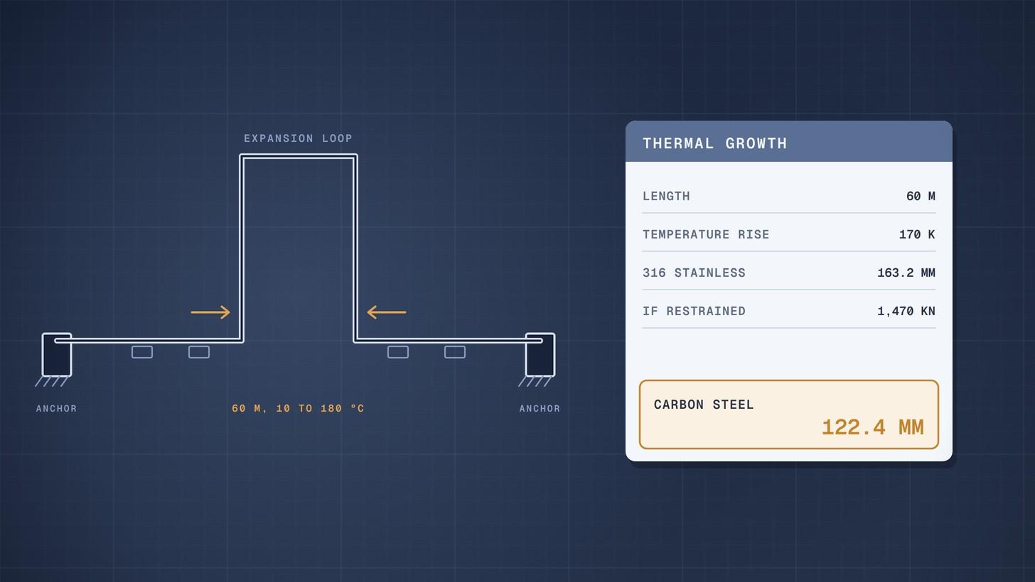
Pipe Thermal Expansion: Worked Example
How to calculate pipe thermal expansion for carbon and stainless steel, what restrained expansion does, and how loops and expansion joints absorb it.
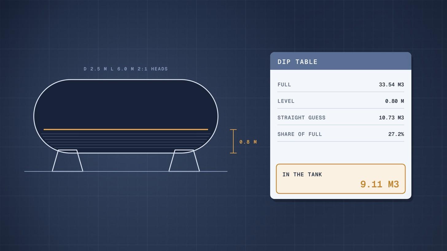
Horizontal Tank Volume When Partly Filled: Worked Example
How to calculate the volume of a partly filled horizontal tank with dished heads, with a worked example and a full dip table you can rebuild in a spreadsheet.
Cooling Water Flow Calculation: Worked Example
How to calculate cooling water flow from heat duty and temperature rise, then size the cooling tower circulation, evaporation and make up water.