
Total Dynamic Head Calculation: Pump Head Worked Example
How to calculate a pump's total dynamic head from static head, pressure difference, line losses and equipment drops, worked through to a rated head for a water transfer pump.
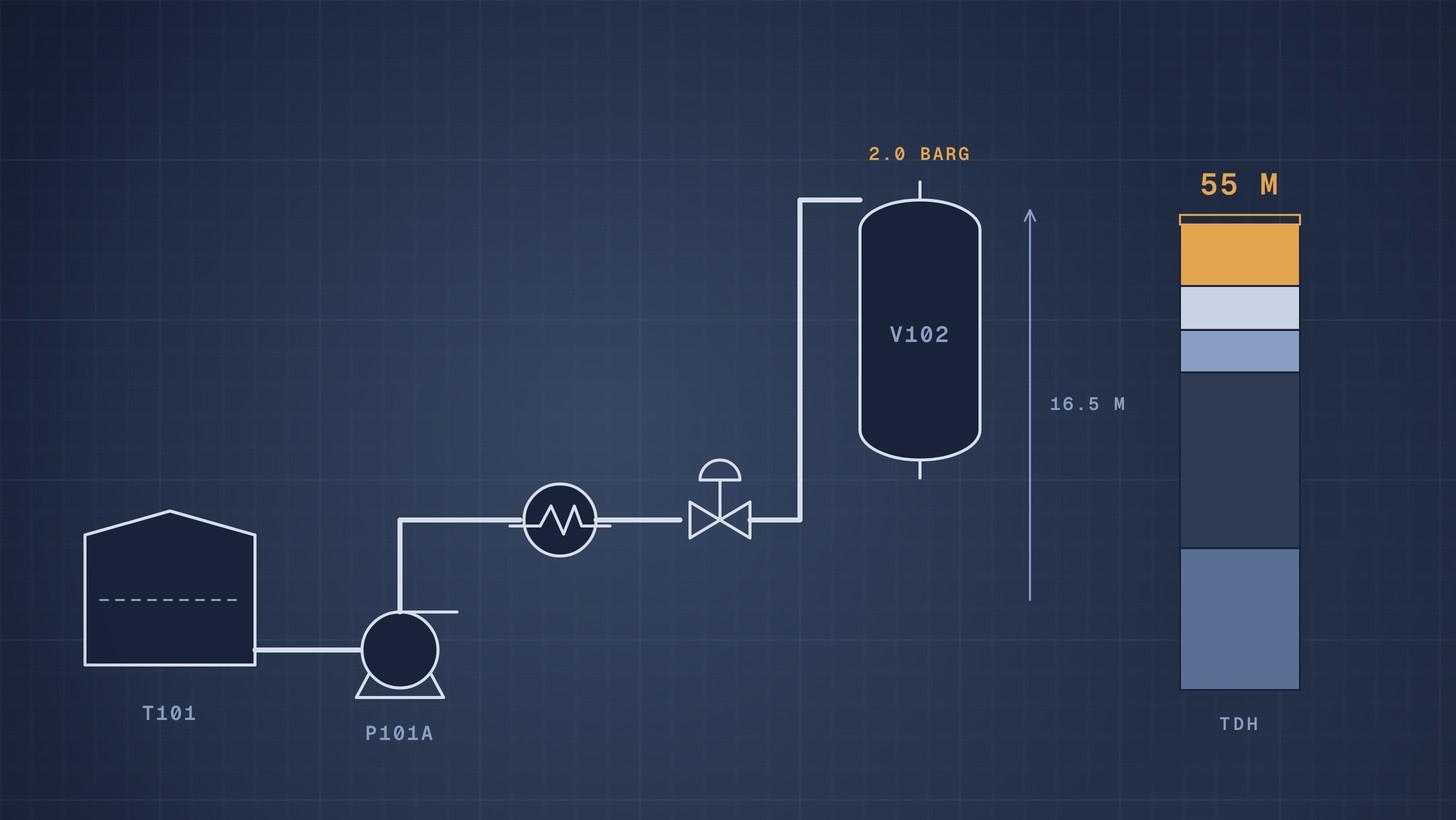
Total dynamic head (TDH) is the head a pump must add to move liquid through the system at the rated flow: the static head (elevation difference plus pressure difference between the two ends) plus every friction loss in the pipe, fittings and equipment. In the worked example below, a water transfer pump needs 54.1 m at 60 m³/h, and we specify 55 m on the datasheet.
Head is measured in metres of the liquid being pumped; KSB defines it as the useful power given to the liquid divided by ρgQ [1]. That is why a pump curve in metres holds for any liquid of normal viscosity, while the pressure and the power change with density.
Why this matters now
The rated head on a pump datasheet decides which pump every supplier offers. Too low, and the pump cannot reach the duty. Too high, and the pump runs to the right of its intended point until someone throttles it, wasting energy for its whole life. KSB notes that the operating point is often matched to the required duty by throttling, and that an exact match between design and duty is rare [2]. The US Department of Energy's pumping sourcebook adds that oversizing for reliability usually ends in less reliability, not more [3].
A head figure with a clear calculation behind it is also a commercial tool. Suppliers can check it, challenge it and quote against it. A round number with no basis invites each supplier to add its own margin, and you end up comparing pumps sized for different duties.
Create and manage RFQs in minutes
ChemCapital handles the entire procurement cycle, from structured RFQs and supplier comparisons to formal purchase orders and delivery tracking.
What goes into total dynamic head
The Hydraulic Institute (HI) splits system head into two parts [4]:
- Static head, which does not change with flow: the elevation difference between the destination and the supply, plus the pressure difference between them divided by ρg.
- Friction head, which rises with the square of flow: pipe losses plus the K value losses of fittings and valves, all multiplied by the velocity head.
To these add the pressure drop of any equipment in the line, such as a heat exchanger, filter or control valve, taken from its datasheet at rated flow.
Three rules keep the sum honest:
- Measure elevations from the liquid surfaces, not the pump. For the supply, use the lowest operating level, because that is when the pump works hardest. If the liquid is below the pump, the suction lift adds to the static head; Geiger Pump and Equipment reminds readers to enter suction elevation as a negative number in that case [5].
- Use the pressures on the liquid surfaces. An open tank is at atmosphere, so its pressure term is zero. A pressurised vessel adds its gauge pressure divided by ρg. If both ends are open, static head is just the difference in levels [4].
- Convert pressure with the right density. HI's metric rule is H = 0.102 × p ÷ s, with H in metres, p in kPa and s the specific gravity [4]. For water, 1 bar is about 10.2 m. For a liquid with an SG of 1.2, the same 1 bar is only 8.5 m.
Worked example: pump P101A
P101A transfers water at 20 °C (998.16 kg/m³ [6]) from atmospheric tank T101 to vessel V102, which is held at 2.0 barg. The layout and equipment drops are illustrative.
- T101 lowest operating level: 1.5 m above the pump centreline
- Discharge pipe outlet in V102: 18.0 m above the pump centreline
- Line losses at 60 m³/h, from our pipe pressure drop calculation: suction 0.085 m and discharge 4.857 m
- Heat exchanger E103: 0.5 bar at rated flow, from the exchanger datasheet
- Flow control valve FV103: 0.7 bar allowed at rated flow
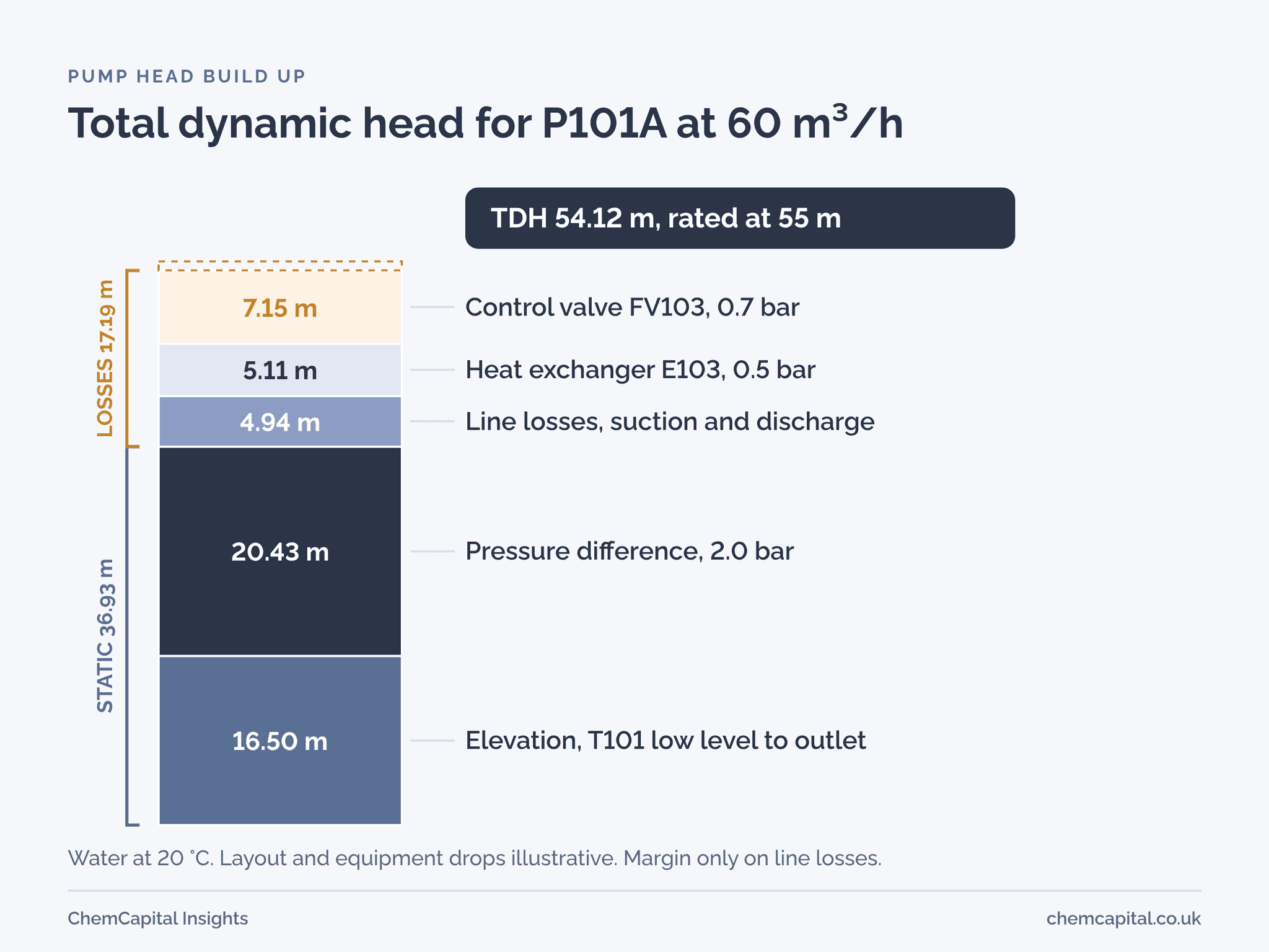
Step 1: elevation. 18.0 minus 1.5 = 16.5 m.
Step 2: pressure difference. V102 is at 2.0 barg and T101 at 0 barg. 200,000 Pa ÷ (998.16 × 9.81) = 20.43 m.
Step 3: line losses. 0.085 + 4.857 = 4.94 m.
Step 4: equipment. E103: 50,000 ÷ (998.16 × 9.81) = 5.11 m. FV103: 70,000 ÷ (998.16 × 9.81) = 7.15 m.
Step 5: add up.
| Item | Head |
|---|---|
| Elevation, T101 low level to outlet | 16.50 m |
| Pressure difference, 2.0 bar | 20.43 m |
| Suction and discharge line losses | 4.94 m |
| Heat exchanger E103 | 5.11 m |
| Control valve FV103 | 7.15 m |
| Total dynamic head at 60 m³/h | 54.12 m |
Step 6: rated head. Static head is known well. Line losses are estimates, because roughness and fitting K values carry real uncertainty. Geiger suggests a 10% to 15% safety factor on friction head estimated by simple methods [5]. Ten per cent of the 4.94 m of line losses is about 0.5 m, giving 54.6 m. We round up and put 60 m³/h at 55 m on the datasheet.
Notice what we did not do. We did not add 10% to the whole 54.1 m. Almost 37 m of it is static head, which does not get more uncertain with time. Putting margin on the static part buys a bigger pump that then runs throttled, and the control valve has to burn off the extra head.
Build the system curve, not just one point
A single duty point hides how the system behaves at other flows. HI builds the system curve by holding static head constant and scaling friction with the square of flow [4].
For P101A, static head is 16.50 + 20.43 = 36.93 m. The line losses plus the exchanger come to 10.05 m at 60 m³/h, so they scale as 10.05 × (Q ÷ 60)². The control valve is left out of the curve because it is the item that adjusts.
| Flow | Static head | Line and exchanger losses | System head without the control valve |
|---|---|---|---|
| 30 m³/h | 36.93 m | 2.51 m | 39.4 m |
| 45 m³/h | 36.93 m | 5.65 m | 42.6 m |
| 60 m³/h | 36.93 m | 10.05 m | 47.0 m |
| 75 m³/h | 36.93 m | 15.70 m | 52.6 m |
Where the pump curve crosses this system curve, the pump runs with the control valve wide open. KSB calls that crossing the operating point [2]. At rated flow the gap between the pump curve and the system curve is the 7 m or so the control valve absorbs. Ask each bidder for the full curve, then overlay this system curve on it. Our guide on how to read a pump curve shows what to look for.
Checking head on a running pump
On site you can measure the head a pump is actually producing with two gauges. Take the discharge pressure minus the suction pressure, convert to metres, and correct for any height difference between the gauges. HI notes that where the velocity is not negligible, the velocity pressure must be added to the gauge reading [4]. In practice that means adding the difference in velocity head between the two nozzles.
Say P101A has a 100 mm suction nozzle and an 80 mm discharge nozzle, with both gauges at the centreline. The suction gauge reads 0.12 barg and the discharge gauge 5.42 barg (illustrative readings). Pressure head: 530,000 ÷ (998.16 × 9.81) = 54.13 m. Velocity is 2.03 m/s in the suction nozzle and 3.49 m/s in the discharge nozzle, so the velocity heads are 0.21 m and 0.62 m, a difference of 0.41 m. Measured head: 54.5 m. Read the flow at the same time and you have a point to plot against the supplier's curve.
Mistakes that change the answer
- Gauge and absolute pressure mixed. Static head uses the difference between the two surfaces, so both must be on the same basis.
- Normal level instead of low level. The pump must meet the duty when the supply tank is nearly empty.
- Water density for a different liquid. A 2 bar difference is 20.4 m of water but 17.0 m of a liquid with SG 1.2. The head changes, and the power changes again because it follows density.
- Equipment drops forgotten. Exchangers, filters, strainers and flowmeters often outweigh the pipe.
- Margin stacked on margin. If the process engineer, the piping designer and the supplier each add 10%, the pump ends up a size too big.
- Suction side ignored. TDH says nothing about cavitation. Check net positive suction head separately; see our NPSH guide.
From head to datasheet and RFQ
The rated head goes on the pump datasheet with the rated flow, the liquid, its density and viscosity at pumping temperature, and the basis of the calculation. Our centrifugal pump datasheet guide lists the fields buyers need. The next step is to turn head into power and a motor size; the pump power calculation carries P101A through to a motor.
When bids arrive, check that every supplier has quoted the same rated point and shown where it sits on the curve. ChemCapital's AI quotation comparison lines up each bid's rated head, efficiency, power and impeller, so a supplier who quoted a different duty point is easy to spot.
Ready to send pump RFQs with a head figure every supplier quotes against? Start a free 14 day ChemCapital trial, with no credit card needed.
Frequently asked questions
How do you calculate total dynamic head?
Add the static head and the friction head. Static head is the elevation difference between the destination and the supply liquid surfaces plus their pressure difference divided by density times g. Friction head is the pipe, fitting and valve losses at the rated flow, plus the pressure drop of equipment such as exchangers and control valves converted to metres.
What is the difference between pump head and pressure?
Head is energy per unit weight of liquid, in metres of that liquid, so a pump produces the same head on water or on a heavier liquid of similar viscosity. Pressure is head times density times g, so the same head gives more pressure, and needs more power, on a denser liquid.
How much margin should I add to pump head?
Put margin on the uncertain part, which is the friction losses, not on the static head. One pump distributor suggests 10% to 15% on friction head estimated by simple methods. Stacking margins from several people leads to an oversized pump that runs throttled.
How do you convert bar to metres of head?
Divide the pressure in pascals by density times g. For water at 20 °C, 1 bar is about 10.2 m. The Hydraulic Institute's metric rule is head in metres equals 0.102 times pressure in kPa divided by specific gravity.
Continue reading
Informational only, not procurement or legal advice. Cited names, frameworks, and statistics belong to their respective owners.
Create and manage RFQs in minutes
ChemCapital handles the entire procurement cycle, from structured RFQs and supplier comparisons to formal purchase orders and delivery tracking.
Start for freeRelated articles
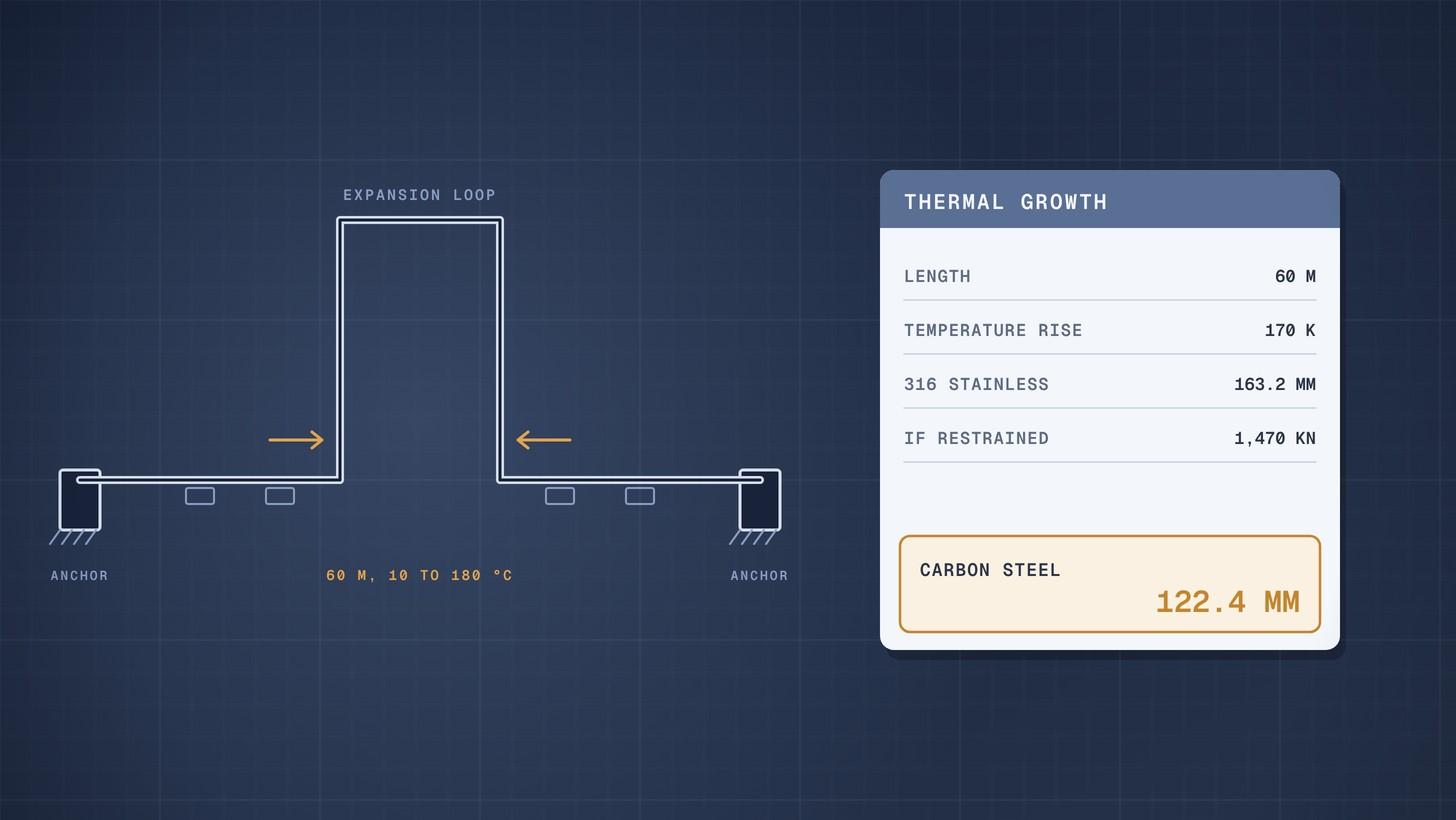
Pipe Thermal Expansion: Worked Example
How to calculate pipe thermal expansion for carbon and stainless steel, what restrained expansion does, and how loops and expansion joints absorb it.
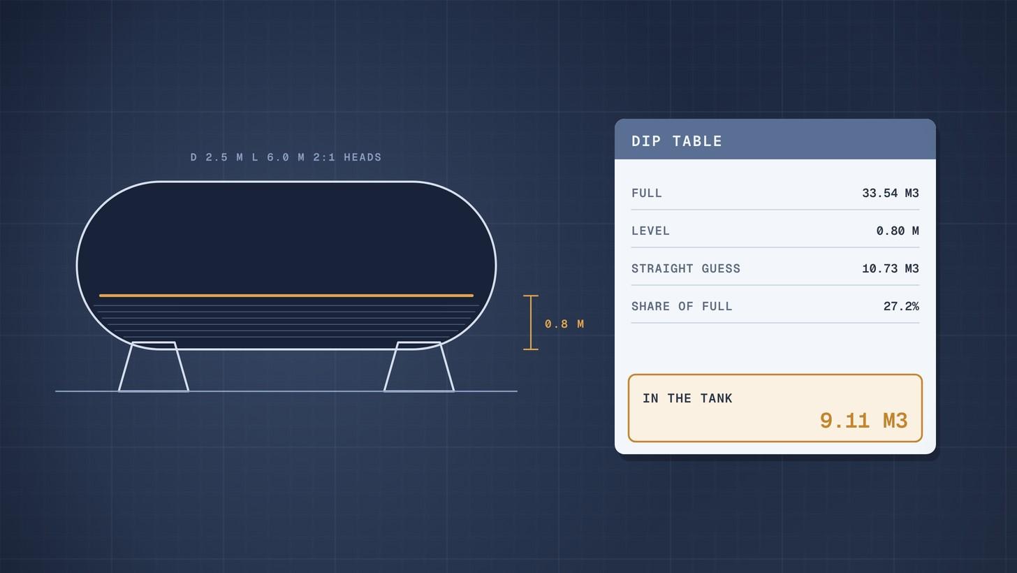
Horizontal Tank Volume When Partly Filled: Worked Example
How to calculate the volume of a partly filled horizontal tank with dished heads, with a worked example and a full dip table you can rebuild in a spreadsheet.
Cooling Water Flow Calculation: Worked Example
How to calculate cooling water flow from heat duty and temperature rise, then size the cooling tower circulation, evaporation and make up water.