
Pipe Pressure Drop Calculation: Darcy Weisbach Worked Example
How to calculate pressure drop in a liquid line with the Darcy Weisbach equation and K values, worked through for 60 m³/h of water in a 4 inch steel line.
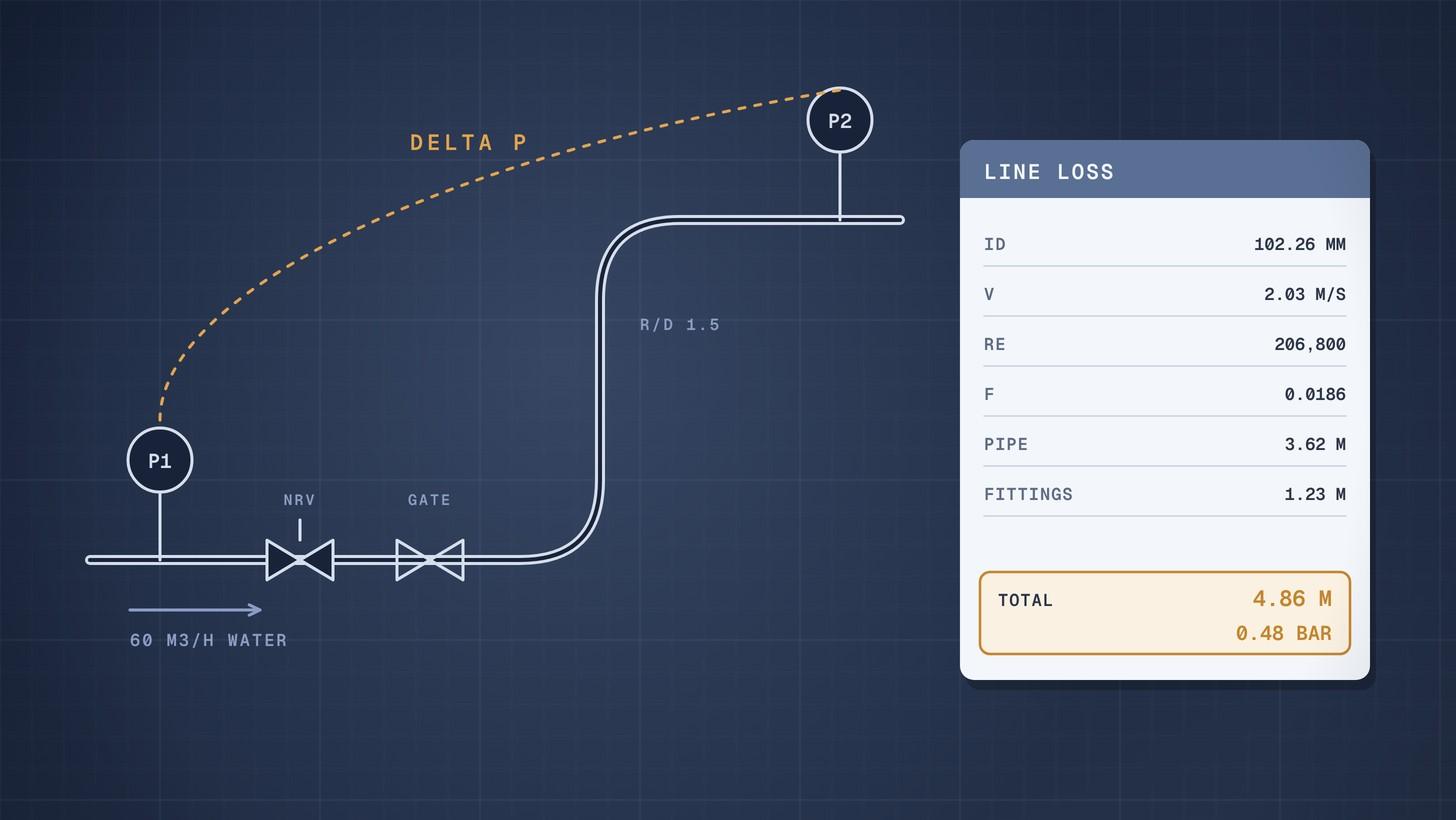
Pipe pressure drop is calculated with the Darcy Weisbach equation: head loss equals the friction factor times length over diameter times the velocity head, plus a K value times the velocity head for each fitting and valve. In the worked example below, 60 m³/h of water at 20 °C through 95 m of 4 inch schedule 40 steel pipe with six elbows, a check valve and a gate valve loses 4.86 m of head, or 0.48 bar.
The same method works for any liquid line in single phase flow. It takes six steps, and every number can be checked on a calculator.
Why this matters now
Pressure drop sets the head the pump must deliver, and head sets the motor and the electricity bill. Get the line losses wrong and you either buy a pump that cannot reach its duty point, or one so oversized that it runs throttled for twenty years. The US Department of Energy's pumping sourcebook warns that oversizing pumps adds energy and maintenance cost, and that oversizing for reliability usually ends in less reliability [1].
It also matters at the RFQ stage. A pump supplier sizes from the rated flow and head on your datasheet. If the head is a guess, every bid is built on that guess, and the bids cannot be compared fairly. A short, transparent pressure drop calculation behind the datasheet lets you defend the numbers when a supplier questions them. It also lets you check whether a supplier's own figure for skid piping or an exchanger is sensible.
Create and manage RFQs in minutes
ChemCapital handles the entire procurement cycle, from structured RFQs and supplier comparisons to formal purchase orders and delivery tracking.
The method in six steps
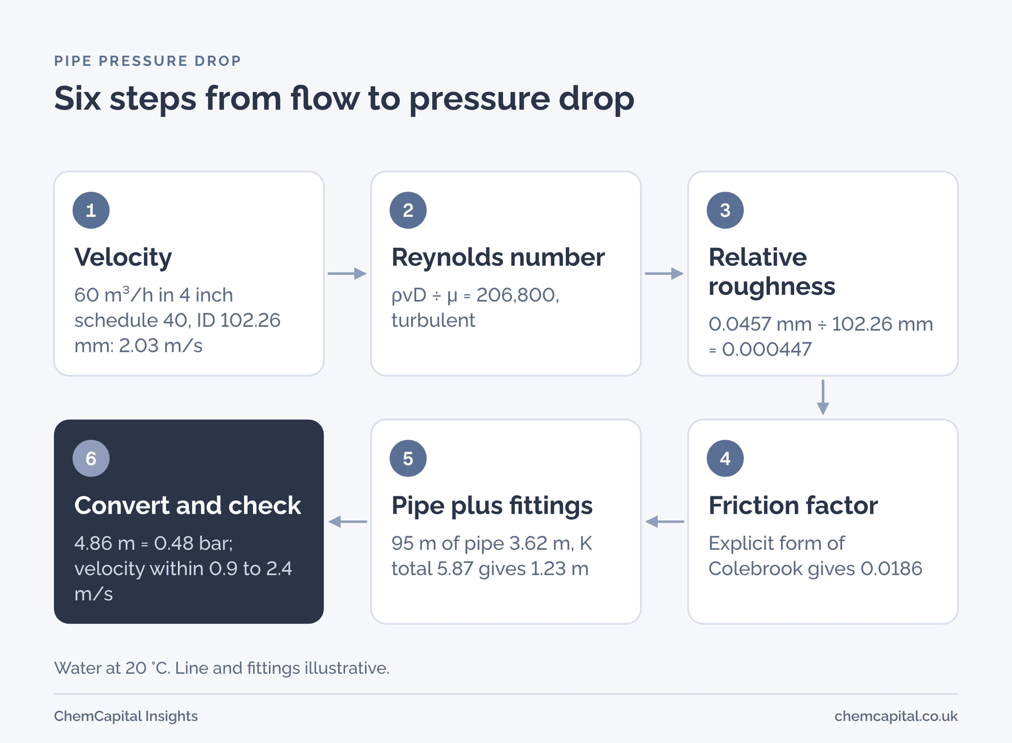
- Velocity. Divide the volumetric flow by the internal cross section area. Use the actual inside diameter for the pipe schedule, never the nominal size.
- Reynolds number. Re = ρvD ÷ μ, with density ρ, velocity v, inside diameter D and dynamic viscosity μ [2].
- Relative roughness. Divide the absolute roughness ε by the inside diameter.
- Friction factor. For laminar flow, f = 64 ÷ Re. For turbulent flow, use the Colebrook equation or an explicit form of it.
- Losses. Pipe loss is f × (L ÷ D) × v² ÷ 2g. Each fitting adds K × v² ÷ 2g [2], [3].
- Convert and check. Head loss in metres times ρg gives pressure drop in pascals. Then check the velocity against normal limits.
The friction factor here is the Darcy friction factor. Some older references use the Fanning factor, which is a quarter of the Darcy value. Mixing the two is a classic error, so check which one a chart or spreadsheet uses before you trust it.
Reynolds number and the friction factor
The Hydraulic Institute (HI) treats flow as laminar when Re is below 2,000, and usually turbulent above about 4,000. Between the two is a critical zone where the friction factor cannot be predicted reliably [2]. Most water and solvent lines in a process plant run well into the turbulent range. Viscous liquids such as heavy oils, syrups and polymer solutions can be laminar, and there f = 64 ÷ Re is exact.
In turbulent flow the friction factor depends on Re and on relative roughness. HI gives the Colebrook equation, which must be solved by iteration, and an explicit form that needs no iteration [2]:
- Explicit form: 1 ÷ √f = 2 × log₁₀[1 ÷ (ε ÷ 3.7D + 5.74 ÷ Re⁰·⁹)]
The explicit form is what most spreadsheets use. In our example it differs from the iterated Colebrook value by less than 1%, which is far smaller than the uncertainty in roughness or fitting losses.
Roughness depends on the pipe material and its condition. HI lists these absolute roughness values for new pipe [2]:
| Pipe material | Absolute roughness ε |
|---|---|
| Drawn tubing (glass, brass, plastic) | 0.0015 mm |
| Stainless steel | 0.015 mm |
| Commercial steel or wrought iron | 0.0457 mm |
| Galvanised iron | 0.152 mm |
| Uncoated cast iron | 0.26 mm |
HI adds that 15% should be added to these values for commercial installations [2]. Old carbon steel lines that have corroded or scaled can be far rougher than new pipe. If you are rating an existing line, measure the actual pressure drop if you can.
Fittings and valves: the K method
Each fitting or valve adds a loss equal to its resistance coefficient K times the velocity head [3]. Typical values for fully turbulent flow are below. They come from Neutrium's summary of the Crane method [4], except the two tank entrances, which HI gives [5], and the outlet, where the whole velocity head is lost by definition.
| Fitting or valve | Typical K |
|---|---|
| Square edged entrance from a tank | 0.5 |
| Inward projecting entrance | 1.0 |
| Long radius 90° elbow (R/D 1.5) | 0.45 |
| Standard 90° elbow (R/D 1) | 0.75 |
| Gate valve, fully open | 0.17 |
| Swing check valve | 2 |
| Globe valve, fully open | 6 |
| Tee, flow through the run | 0.4 |
| Tee, flow through the branch | 1 |
| Pipe outlet into a vessel | 1 |
Treat these as estimates. HI notes that K falls as most valves and fittings get larger, and gives ranges of variation of 30% to 50% for common flanged fittings and valves. For a flanged swing check valve the range is plus 200% to minus 80% [3]. Neutrium also warns that a K value is inaccurate at sizes other than the one it was measured at [4]. For a critical line, use the valve maker's own flow data or a size dependent method.
Equipment in the line is a separate item. A heat exchanger, filter, flowmeter or control valve has its own pressure drop at the rated flow. Take it from the vendor's datasheet, not from a K table. Our guide to control valve sizing explains how to allow for the valve.
Worked example: a 4 inch water discharge line
Pump P101A transfers water at 20 °C from tank T101 to vessel V102. The line and its fittings are illustrative. The pipe and water data are sourced.
Data
- Flow: 60 m³/h = 0.016667 m³/s
- Water at 20 °C: density 998.16 kg/m³, viscosity 1.0014 mPa·s [6]
- Discharge line: 95 m of 4 inch schedule 40 carbon steel, inside diameter 102.26 mm [7]
- Roughness: 0.0457 mm, new commercial steel [2]
- Fittings: six long radius elbows (0.45 each), one swing check valve (2), one gate valve (0.17) and the outlet into V102 (1). Total K = 5.87
Step 1: velocity. Area = π ÷ 4 × 0.10226² = 0.008213 m². Velocity = 0.016667 ÷ 0.008213 = 2.03 m/s.
Step 2: Reynolds number. Re = 998.16 × 2.03 × 0.10226 ÷ 0.0010014 = 206,800. Fully turbulent.
Step 3: relative roughness. ε ÷ D = 0.0457 ÷ 102.26 = 0.000447.
Step 4: friction factor. The explicit form gives f = 0.0186. Iterating Colebrook gives 0.0185.
Step 5: losses. The velocity head is v² ÷ 2g = 2.03² ÷ (2 × 9.81) = 0.210 m.
- Pipe: 0.0186 × (95 ÷ 0.10226) × 0.210 = 3.62 m
- Fittings: 5.87 × 0.210 = 1.23 m
- Total: 4.86 m of water
Step 6: convert and check. 4.86 m × 998.16 × 9.81 = 47,600 Pa, or 0.48 bar. The straight pipe alone works out at 0.37 bar per 100 m. Velocity is 2.03 m/s. Michael Smith Engineers, a UK pump supplier, quotes 0.9 to 2.4 m/s as typical for water [8], so the line size is reasonable.
The suction line is worked the same way. With 8 m of 6 inch schedule 40 pipe (inside diameter 154.05 mm [7]), a square edged entrance, a gate valve and one long radius elbow (total K 1.12), velocity is 0.89 m/s and the loss is only 0.085 m. Short, generous suction lines like this protect the pump's net positive suction head; see our guide to NPSH.
| Line | Inside diameter | Velocity | Reynolds number | f | Pipe loss | Fittings loss | Total |
|---|---|---|---|---|---|---|---|
| Suction, 6 inch, 8 m | 154.05 mm | 0.89 m/s | 137,300 | 0.0186 | 0.039 m | 0.046 m | 0.085 m |
| Discharge, 4 inch, 95 m | 102.26 mm | 2.03 m/s | 206,800 | 0.0186 | 3.62 m | 1.23 m | 4.86 m |
What line size and viscosity do to the answer
Now run the same discharge line in 3 inch schedule 40 pipe, inside diameter 77.93 mm [7]. Velocity rises to 3.49 m/s and the velocity head to 0.622 m. The total loss becomes 18.0 m, or 1.76 bar, against 4.86 m for the 4 inch line.
That is nearly four times the loss for one size down. Friction loss rises with roughly the square of velocity, and velocity rises with the inverse square of diameter. The extra 13 m of head would push the pump up a size and add to the power bill every hour it runs. This is why line sizing and pump sizing belong in the same calculation.
Viscosity can matter even more. Suppose the same 4 inch line carried an oil with a density of 900 kg/m³ and a viscosity of 200 mPa·s, both illustrative. Velocity is unchanged at 2.03 m/s, but Re falls to about 930, so the flow is laminar. The friction factor becomes 64 ÷ 934 = 0.0685, nearly four times the water value, and the straight pipe alone loses 13.4 m of oil, or 1.18 bar. Roughness plays no part in laminar flow. If the oil thickens further on a cold morning, the loss rises in proportion to the viscosity, so size the pump for the coldest liquid it will see.
Roughness matters much less. Adding HI's 15% allowance to the 4 inch case raises the friction factor from 0.0186 to 0.0190 and the total loss from 4.86 m to 4.93 m. For new steel pipe, the fittings count and the line size dominate.
Where the pressure drop goes next
The line losses feed the pump head. Total dynamic head adds the static lift, the difference in pressure between the two vessels, the line losses and the drops across equipment such as exchangers and control valves. Our total dynamic head calculation carries this example on to a rated head for P101A, and the pump power calculation turns that head into kilowatts and a motor size.
Record the result where the project can find it. The line list is the natural home for line size, design flow and calculated pressure drop; see our guide to the line list, valve list and instrument index.
Mistakes that change the answer
- Nominal size used as the diameter. A 4 inch schedule 40 pipe has an inside diameter of 102.26 mm, not 101.6 mm, and schedule 80 is smaller still. Pipe loss varies roughly with the inverse fifth power of diameter, so small diameter errors grow.
- Fanning factor in a Darcy equation. The result is four times too low.
- Fittings left out. Here they add a third to the pipe loss. In short skid piping they can be most of it.
- Viscosity at the wrong temperature. Many liquids thicken sharply when cold. Check start up and winter cases as well as the normal duty.
- Two phase or flashing flow. This method is for single phase liquid. Gas, steam and flashing liquids need other methods.
- Equipment drops from a K table. Use the vendor's figure at rated flow, and ask for it in the RFQ.
Turning the calculation into a better RFQ
A pump RFQ should carry the rated flow, the calculated head with the basis behind it, and the liquid properties at the pumping temperature. Our centrifugal pump datasheet guide lists the fields. When bids come back, compare them on the same duty point and the same assumptions. ChemCapital's AI quotation comparison puts each supplier's offered head, efficiency and power side by side, so a bid quoted at a different duty point stands out before the technical review.
Ready to send pump RFQs built on numbers you can defend? Start a free 14 day ChemCapital trial, with no credit card needed.
Frequently asked questions
How do you calculate pressure drop in a pipe?
Work out the velocity from the flow and the inside diameter, then the Reynolds number, the relative roughness and the Darcy friction factor. Pipe head loss is the friction factor times length over diameter times v squared over 2g. Add K times v squared over 2g for each fitting and valve, then multiply the total head by density and g to get pressure drop in pascals.
What is the Darcy Weisbach equation?
It gives the friction head loss in a pipe as hf = f × (L ÷ D) × v² ÷ 2g, where f is the Darcy friction factor, L the length, D the inside diameter and v the mean velocity. It works for any liquid in single phase flow, laminar or turbulent, as long as the friction factor is chosen for the flow regime.
What roughness should I use for steel pipe?
The Hydraulic Institute lists 0.0457 mm for new commercial steel and 0.015 mm for stainless steel, and suggests adding 15% for commercial installations. Old or corroded carbon steel can be much rougher, so measure the actual pressure drop when rating an existing line.
What is a good velocity for water in a pipe?
For water and similar clean liquids, about 1 to 2 m/s is commonly accepted, and typical water velocities run from about 0.9 to 2.4 m/s. Slurries with settling solids need higher velocities to avoid deposits, and shear sensitive or foaming liquids need lower ones.
Continue reading
Informational only, not procurement or legal advice. Cited names, frameworks, and statistics belong to their respective owners.
Create and manage RFQs in minutes
ChemCapital handles the entire procurement cycle, from structured RFQs and supplier comparisons to formal purchase orders and delivery tracking.
Start for freeRelated articles
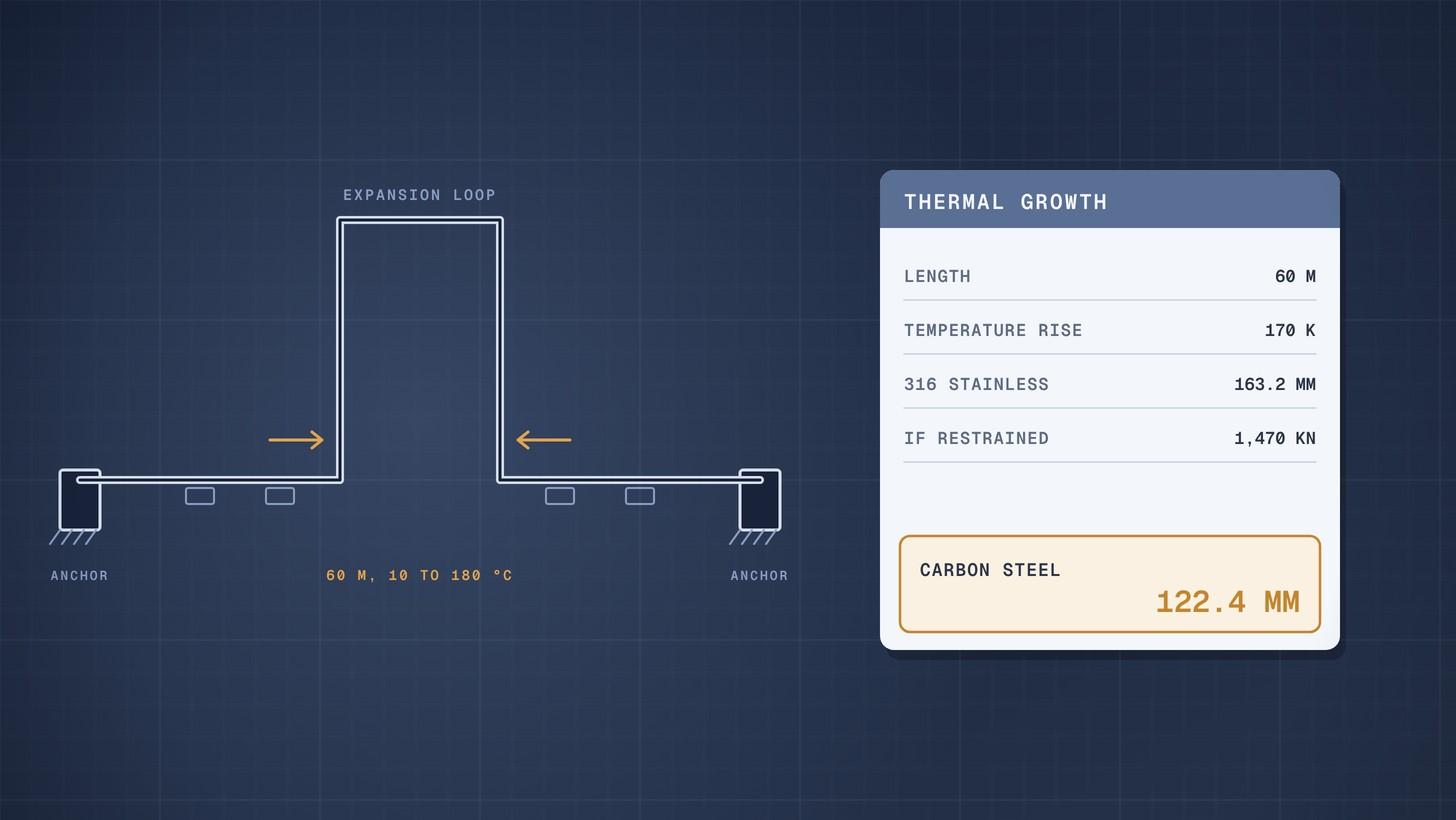
Pipe Thermal Expansion: Worked Example
How to calculate pipe thermal expansion for carbon and stainless steel, what restrained expansion does, and how loops and expansion joints absorb it.
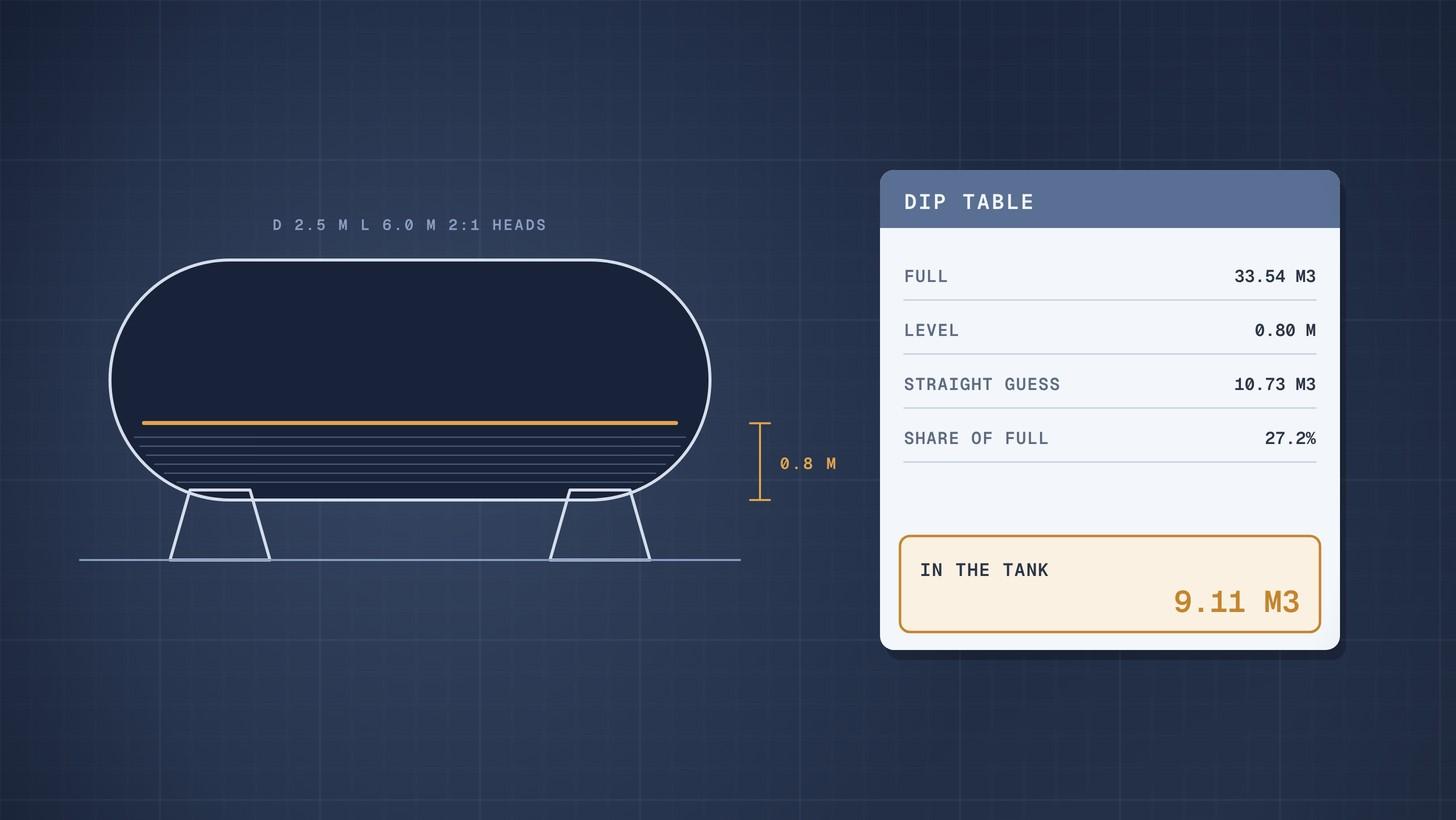
Horizontal Tank Volume When Partly Filled: Worked Example
How to calculate the volume of a partly filled horizontal tank with dished heads, with a worked example and a full dip table you can rebuild in a spreadsheet.
Cooling Water Flow Calculation: Worked Example
How to calculate cooling water flow from heat duty and temperature rise, then size the cooling tower circulation, evaporation and make up water.